SLIDING ROOF HOUSING INSTALLATION

-
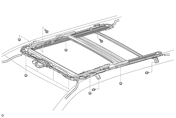
INSTALL SLIDING ROOF HOUSING SUB-ASSEMBLY
-
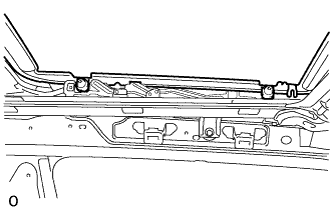
Temporarily install the sliding roof housing sub-assembly with the 4 bolts (vehicle body side) and 8 nuts.
-
Tighten the 8 nuts.
- Torque:
- 5.5 N*m { 56 kgf*cm, 49 in.*lbf }
-
Tighten the 4 bolts.
- Torque:
- 8.0 N*m { 82 kgf*cm, 71 in.*lbf }
-
Connect the 4 drain hoses.
-
-
INSTALL SLIDING ROOF WEATHERSTRIP
-
Install the sliding roof weatherstrip as follows:
-
Position the joint of the sliding roof weatherstrip at the rear center.
-
Align the alignment mark on the sliding roof weatherstrip with the middle marks at the corners of the sliding roof glass sub-assembly and install the sliding roof weatherstrip.
-
Install the lip of the sliding roof weatherstrip firmly.
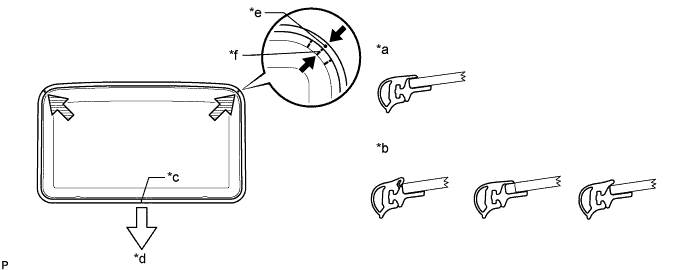
Text in Illustration *a Correct *b Incorrect *c Joint *d Vehicle Rear *e Alignment Mark *f Middle Mark
-
-
-
INSTALL SLIDING ROOF GLASS SUB-ASSEMBLY
-
Using a T25 "TORX" driver, temporarily install the sliding roof glass sub-assembly with the 4 screws.
-
Perform a level check.
-
Check the difference in the level between the roof panel and upper surface of the weatherstrip labeled "a" when the sliding roof glass is fully closed.
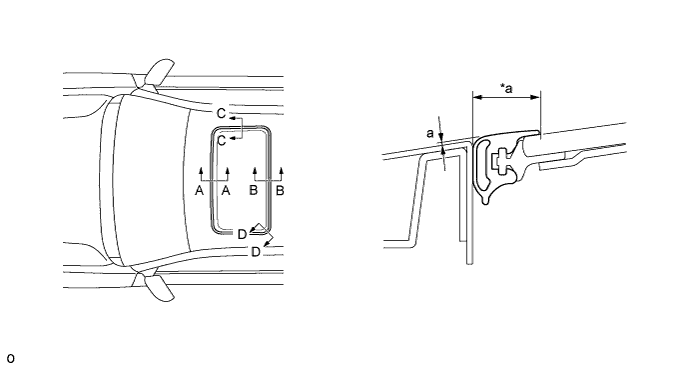
Text in Illustration *a Even - - Standard Area Specified Condition A - A -2.0 to 1.0 mm (-0.0787 to 0.0394 in.) B - B -1.0 to 2.0 mm (-0.0394 to 0.0787 in.) C - C -1.5 to 1.5 mm (-0.0591 to 0.0591 in.) D - D -1.0 to 1.5 mm (-0.0394 to 0.0591 in.) Tech Tips
"+" represents the condition that the glass is above the panel level. "-" represents the condition that the glass is below the panel level.
-
Perform a gap check.
Check the gap between the roof panel and roof glass.
Note
The gap must be even all around.
-
-
Using a T25 "TORX" driver, tighten the 4 screws.
- Torque:
- 5.5 N*m { 56 kgf*cm, 49 in.*lbf }
-
-
CHECK FOR WATER LEAK
-
After adjusting the sliding roof glass sub-assembly, check for water leakage into the vehicle interior.
If there are any leaks, readjust the sliding roof glass sub-assembly.
-
-
INSTALL SLIDING ROOF SIDE GARNISH LH
-
Attach the 5 claws to install the sliding roof side garnish LH.
-
-
INSTALL SLIDING ROOF SIDE GARNISH RH
Tech Tips
Use the same procedure described for the LH side.
-
INSTALL TELEVISION DISPLAY BRACKET A (w/ Rear Seat Entertainment System)
-
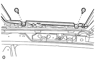
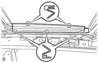
Install the television display bracket A with the 4 nuts.
- Torque:
- 9.0 N*m { 92 kgf*cm, 80 in.*lbf }
Text in Illustration 
Front Side
-
-
INSTALL TELEVISION DISPLAY ASSEMBLY (w/ Rear Seat Entertainment System)
-
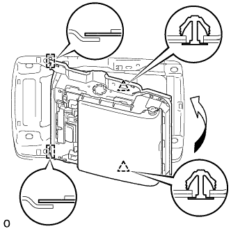
Attach the television display assembly to the 2 guides on the front side of the bracket by moving it in the direction of the arrow in the illustration, and then attach 2 new clips to temporarily install the television display assembly.
-
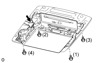
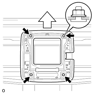
Install the television display assembly with the 4 bolts in the order shown in the illustration.
- Torque:
- 8.5 N*m { 87 kgf*cm, 75 in.*lbf }
-
Connect the connector.
-
-
INSTALL REAR NO. 3 ROOF AIR DUCT (for Dual Air Conditioning System)
-
Install the duct with the clip.
-
-
INSTALL REAR NO. 5 ROOF AIR DUCT (for Dual Air Conditioning System)
-
Install the duct with the clip.
-
-
INSTALL CURTAIN SHIELD AIRBAG ASSEMBLY LH
-
INSTALL CURTAIN SHIELD AIRBAG ASSEMBLY RH
Tech Tips
Use the same procedure described for the LH side.
-
INSTALL ROOF HEADLINING ASSEMBLY (for 3 Door)
-
INSTALL ROOF HEADLINING ASSEMBLY (for 5 Door)
-
CONNECT CABLE TO NEGATIVE BATTERY TERMINAL
Note
When disconnecting the cable, some systems need to be initialized after the cable is reconnected Click here.
-
CHECK SRS WARNING LIGHT