SLIDING ROOF SYSTEM, Diagnostic DTC:B2342

| DTC Code | DTC Name |
|---|---|
| B2342 | Switch Failure |
DESCRIPTION
This DTC is stored when the sliding roof drive gear sub-assembly detects that the sliding roof switch in the map light assembly is stuck for 30 seconds or more.
| DTC Code | DTC Detection Condition | Trouble Area |
|---|---|---|
| B2342 | The sliding roof drive gear sub-assembly detects that the sliding roof switch in the map light assembly is stuck for 30 seconds or more. |
|
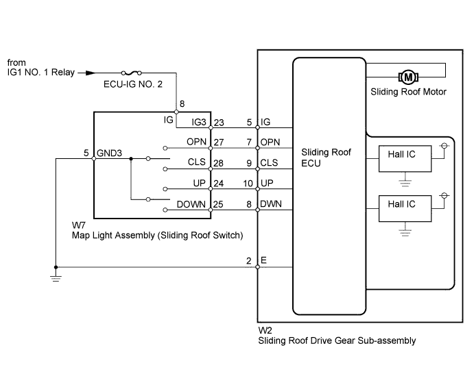
WIRING DIAGRAM
INSPECTION PROCEDURE
Note
When the sliding roof drive gear sub-assembly is removed and reinstalled or replaced, the sliding roof drive gear sub-assembly must be initialized Click here.
PROCEDURE
-
CHECK FOR DTC
-
Clear the DTCs Click here.
-
Check for DTCs Click here.
Result Result Proceed to DTC B2342 is output A DTC B2342 is not output B
B 
USE SIMULATION METHOD TO CHECK Click here
A 
-
-
READ VALUE USING INTELLIGENT TESTER (SLIDING ROOF)
-
Using the intelligent tester, read the Data List Click here.
Sliding Roof Tester Display Measurement Item/Range Normal Condition Diagnostic Note Open Switch Failure (Past) Slide open switch failure signal (Past) / ON or OFF ON: Slide open switch signal failure (Past)
OFF: No slide open switch signal failure (Past)
- Close Switch Failure (Past) Slide close switch failure signal (Past) / ON or OFF ON: Slide close switch signal failure (Past)
OFF: No slide close switch signal failure (Past)
- Up Switch Failure (Past) Tilt up switch failure signal (Past) / ON or OFF ON: Tilt up switch signal failure (Past)
OFF: No tilt up switch signal failure (Past)
- Down Switch Failure (Past) Tilt down switch failure signal (Past) / ON or OFF ON: Tilt down switch signal failure (Past)
OFF: No tilt down switch signal failure (Past)
- Open Switch Failure (Current) Slide open switch failure signal (Current) / ON or OFF ON: Slide open switch signal failure (Current)
OFF: No slide open switch signal failure (Current)
- Close Switch Failure (Current) Slide close switch failure signal (Current) / ON or OFF ON: Slide close switch signal failure (Current)
OFF: No slide close switch signal failure (Current)
- Up Switch Failure (Current) Tilt up switch failure signal (Current) / ON or OFF ON: Tilt up switch signal failure (Current)
OFF: No tilt up switch signal failure (Current)
- Down Switch Failure (Current) Tilt down switch failure signal (Current) / ON or OFF ON: Tilt down switch signal failure (Current)
OFF: No tilt down switch signal failure (Current)
- OK "OFF" appears on the intelligent tester screen.
NG 
INSPECT MAP LIGHT ASSEMBLY Click here
OK 
REPLACE SLIDING ROOF DRIVE GEAR SUB-ASSEMBLY Click here
-
-
INSPECT MAP LIGHT ASSEMBLY
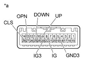
Text in Illustration *a Component without harness connected
(Map Light Assembly)
-
Remove the map light assembly Click here.
-
Measure the resistance according to the value(s) in the table below.
Standard Resistance Tester Connection Switch Condition Specified Condition 8 (IG) - 23 (IG3) Always Below 1 Ω 24 (UP) - 5 (GND3) Tilt up switch pressed Below 1 Ω 24 (UP) - 5 (GND3) Tilt up switch not pressed 10 kΩ or higher 25 (DOWN) - 5 (GND3) Tilt down switch pressed Below 1 Ω 25 (DOWN) - 5 (GND3) Tilt down switch not pressed 10 kΩ or higher 27 (OPN) - 5 (GND3) Slide open switch pressed Below 1 Ω 27 (OPN) - 5 (GND3) Slide open switch not pressed 10 kΩ or higher 28 (CLS) - 5 (GND3) Slide close switch pressed Below 1 Ω 28 (CLS) - 5 (GND3) Slide close switch not pressed 10 kΩ or higher
NG
REPLACE MAP LIGHT ASSEMBLY Click here
OK
-
-
CHECK HARNESS AND CONNECTOR (SLIDING ROOF ECU - SLIDING ROOF SWITCH, BATTERY AND BODY GROUND)
-
Disconnect the W2 ECU connector.
-
Disconnect the W7 switch connector.
-
Measure the resistance and voltage according to the value(s) in the table below.
Standard Resistance Tester Connection Condition Specified Condition W2-10 (UP) - W7-24 (UP) Always Below 1 Ω W2-8 (DWN) - W7-25 (DOWN) Always Below 1 Ω W2-7 (OPN) - W7-27 (OPN) Always Below 1 Ω W2-9 (CLS) - W7-28 (CLS) Always Below 1 Ω W7-5 (GND3) - Body ground Always Below 1 Ω W2-2 (E) - Body ground Always Below 1 Ω W2-5 (IG) - W7-23 (IG3) Always Below 1 Ω W2-10 (UP) or W7-24 (UP) - Body ground Always 10 kΩ or higher W2-8 (DWN) or W7-25 (DOWN) - Body ground Always 10 kΩ or higher W2-7 (OPN) or W7-27 (OPN) - Body ground Always 10 kΩ or higher W2-9 (CLS) or W7-28 (CLS) - Body ground Always 10 kΩ or higher W2-5 (IG) or W7-23 (IG3) - Body ground Always 10 kΩ or higher Standard Voltage Tester Connection Switch Condition Specified Condition W7-8 (IG) - Body ground Ignition switch off Below 1 V W7-8 (IG) - Body ground Ignition switch ON 11 to 14 V
NG
REPAIR OR REPLACE HARNESS OR CONNECTOR
OK
REPLACE SLIDING ROOF DRIVE GEAR SUB-ASSEMBLY Click here
-