POWER WINDOW REGULATOR MOTOR (for Front Door) INSTALLATION

Tech Tips
-
Use the same procedure for the RH and LH sides.
-
The procedure listed below is for the LH side.
-
A bolt without a torque specification is shown in the standard bolt chart Click here.
-
INSTALL FRONT POWER WINDOW REGULATOR MOTOR ASSEMBLY LH
-
Apply MP grease to the sliding and rotating areas of the regulator motor.
-
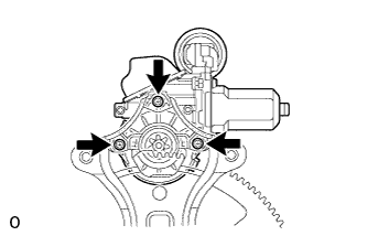
Using a T25 "TORX" socket wrench, install the power window regulator motor with the 3 screws.
- Torque:
- 5.4 N*m { 55 kgf*cm, 48 in.*lbf }
Tech Tips
A new front window regulator uses self-tapping screws to thread new installation holes when the self-tapping screws are inserted.
-
-
INSTALL FRONT DOOR WINDOW REGULATOR SUB-ASSEMBLY LH
-
Apply MP grease to the sliding parts of the front door window regulator assembly.
-
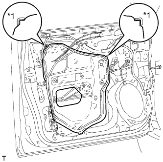
Install the temporary bolt to the front door window regulator assembly.
-
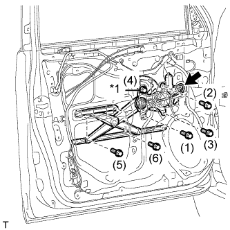
Text in Illustration *1 Temporary Bolt Temporarily install the front door window regulator assembly with the temporary bolt.
-
Temporarily install the 5 bolts, and then tighten the temporary bolt and 5 bolts.
- Torque:
- 8.0 N*m { 82 kgf*cm, 71 in.*lbf }
Tech Tips
Tighten the bolts in the order shown in the illustration.
-
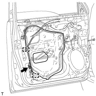
Connect the connector.
-
-
INSTALL FRONT DOOR GLASS SUB-ASSEMBLY LH
-
Connect the cable to the negative (-) battery terminal.
-
Connect the power window regulator master switch assembly and move the front door glass sub-assembly so that the door glass bolt installation locations can be seen.
-
Disconnect the cable from the negative (-) battery terminal and power window regulator master switch assembly.
CAUTION:
Wait at least 90 seconds after disconnecting the cable from the negative (-) battery terminal to disable the SRS system Click here.
-
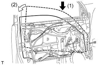
Insert the front door glass sub-assembly into the front door panel along the front door glass run as indicated by the arrows in the order shown in the illustration.
-
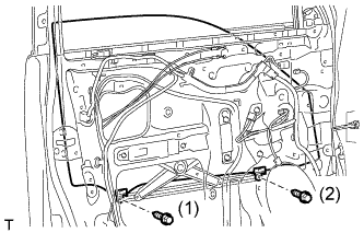
Install the front door glass sub-assembly with the 2 bolts.
- Torque:
- 5.5 N*m { 56 kgf*cm, 49 in.*lbf }
Tech Tips
Tighten the bolts in the order shown in the illustration.
-
-
INSTALL FRONT DOOR SERVICE HOLE COVER LH
-
Apply new butyl tape to the front door panel.
-
Text in Illustration *1 Reference Point Pass the front door lock remote control cable assembly and front door inside locking cable assembly through a new front door service hole cover.
-
Attach the front door service hole cover using the reference points on the front door panel.
Note
-
There should be no wrinkles or folds after attaching the service hole cover.
-
After attaching the service hole cover, check the seal quality.
Note
Securely install the front door service hole cover preventing wrinkles and air bubbles.
-
-
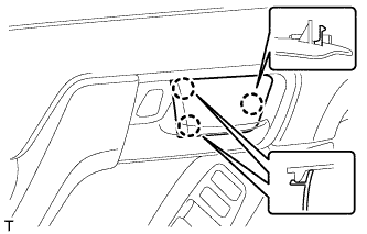
Attach the 2 clamps.
-
Install the bolt to the front door wire.
-
-
INSTALL FRONT NO. 1 SPEAKER ASSEMBLY
-
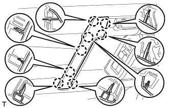
Temporarily install the speaker by attaching the 2 claws of the speaker to the door panel.
-
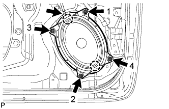
Install the speaker with the 4 screws in the order shown in the illustration.
-
Connect the speaker connector.
Note
Do not touch the cone of the speaker.
-
-
INSTALL FRONT DOOR INNER GLASS WEATHERSTRIP LH
-
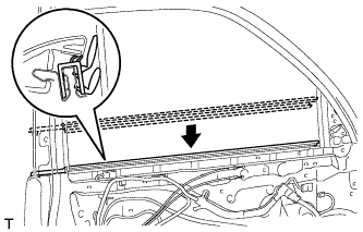
Install the front door inner glass weatherstrip.
-
-
INSTALL FRONT DOOR TRIM BOARD SUB-ASSEMBLY LH
-
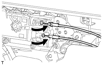
Connect the front door lock remote control cable assembly and front door inside locking cable assembly.
-
Connect 2 connectors.
-
w/ Seat Position Memory System:
-
Connect the connectors.
-
-
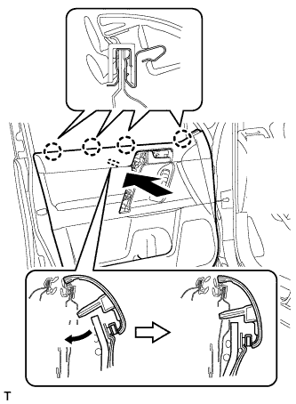
Attach the front door trim board sub-assembly by attaching the 4 claws of the front door inner glass weatherstrip as shown in the illustration.
-
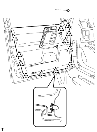
Attach the 12 clips and front door trim board retainer to install the front door trim board sub-assembly.
-
Install the 3 screws.
-
-
INSTALL ASSIST GRIP COVER LH
-
Attach the 8 claws to install the assist grip cover.
-
-
INSTALL FRONT DOOR LOWER FRAME BRACKET GARNISH LH
-
Attach the 2 claws to install the front door lower frame bracket garnish.
-
-
INSTALL NO. 2 DOOR INSIDE HANDLE BEZEL LH
-
Attach the 3 claws to install the inside handle bezel.
-
-
CONNECT CABLE TO NEGATIVE BATTERY TERMINAL
Note
When disconnecting the cable, some systems need to be initialized after the cable is reconnected Click here.
-
INITIALIZE POWER WINDOW CONTROL SYSTEM
-
Initialize the power window control system Click here.
-