WINDOW DEFOGGER SYSTEM Rear Window Defogger System does not Operate
DESCRIPTION
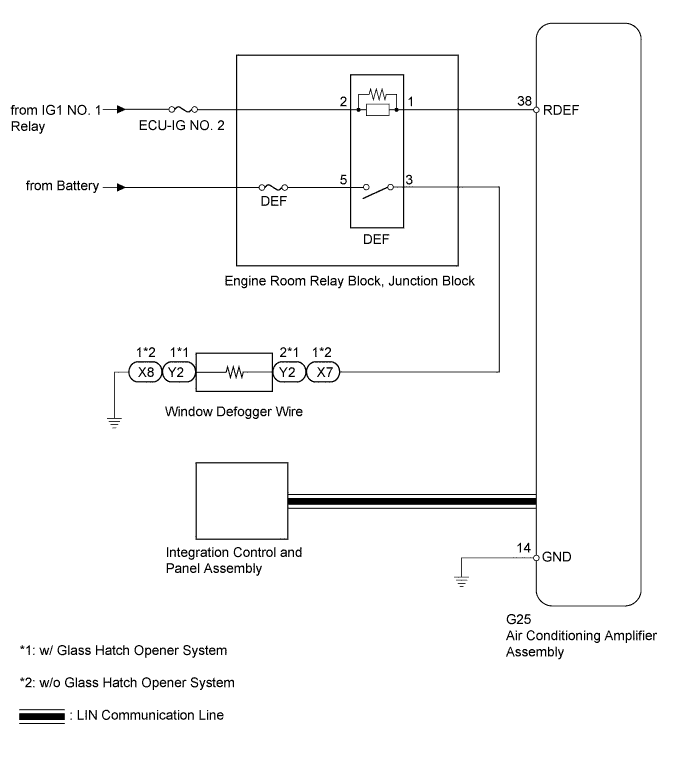
When the rear window defogger switch is turned on, a rear window defogger activation request signal is sent via the LIN communication line to the air conditioning amplifier.
WIRING DIAGRAM
INSPECTION PROCEDURE
Note
-
Inspect the fuses for circuits related to this system before performing the following inspection procedure.
-
Since the window defogger system has functions that use LIN communication, first confirm that there is no malfunction in the communication system by inspecting the LIN communication functions in accordance with the "How to Proceed with Troubleshooting" procedures. Then, conduct the following inspection procedure.
PROCEDURE
-
PERFORM ACTIVE TEST USING INTELLIGENT TESTER (DEFOGGER RELAY [REAR])
-
Using the intelligent tester, perform the Active Test Click here.
Air Conditioner Tester Display Test Part Control Range Diagnostic Note Defogger Relay (Rear) DEF relay operation OFF/ON - OK The DEF relay operates normally.
NG 
INSPECT DEF RELAY Click here
OK 
-
-
REPLACE INTEGRATION CONTROL AND PANEL ASSEMBLY
-
Temporarily replace the heater control with a new or normally functioning one Click here.
-
Check the rear defogger function.
OK The window defogger function operates normally.
NG 
REPLACE AIR CONDITIONING AMPLIFIER ASSEMBLY Click here
OK 
END (INTEGRATION CONTROL AND PANEL ASSEMBLY IS DEFECTIVE)
-
-
INSPECT DEF RELAY
-
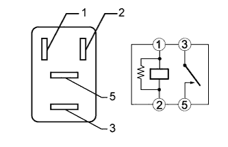
Remove the DEF relay from the engine room relay block, junction block.
-
Measure the resistance according to the value(s) in the table below.
Standard Resistance Tester Connection Condition Specified Condition 3 - 5 Battery voltage applied between terminals 1 and 2 Below 1 Ω 3 - 5 Battery voltage not applied between terminals 1 and 2 10 kΩ or higher
NG
REPLACE DEF RELAY
OK
-
-
CHECK HARNESS AND CONNECTOR (DEF RELAY - BATTERY AND BODY GROUND)
-
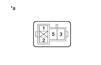
Text in Illustration *a Front view of wire harness connector
(to DEF Relay)
Remove the DEF relay from the engine room relay block, junction block.
-
Measure the voltage according to the value(s) in the table below.
Standard Voltage Tester Connection Switch Condition Specified Condition DEF relay terminal 2 - Body ground Ignition switch off Below 1 V DEF relay terminal 2 - Body ground Ignition switch ON 11 to 14 V DEF relay terminal 5 - Body ground Always 11 to 14 V
NG
REPAIR OR REPLACE HARNESS OR CONNECTOR
OK
-
-
CHECK HARNESS AND CONNECTOR (AIR CONDITIONING AMPLIFIER ASSEMBLY - DEF RELAY AND BODY GROUND)
-
Disconnect the G25 air conditioning amplifier connector.
-
Remove the DEF relay from the engine room relay block, junction block.
-
Measure the resistance according to the value(s) in the table below.
Standard Resistance Tester Connection Condition Specified Condition DEF relay terminal 1 - G25-38 (RDEF) Always Below 1 Ω G25-14 (GND) - Body ground Always Below 1 Ω G25-38 (RDEF) - Body ground Always 10 kΩ or higher
NG
REPAIR OR REPLACE HARNESS OR CONNECTOR
OK
-
-
INSPECT AIR CONDITIONING AMPLIFIER ASSEMBLY
-
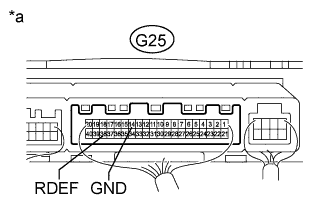
Text in Illustration *a Component with harness connected
(Air Conditioning Amplifier Assembly)
Measure the voltage according to the value(s) in the table below.
Standard Voltage Tester Connection Switch Condition Specified Condition G25-38 (RDEF) - G25-14 (GND) Ignition switch ON, defogger switch on 11 to 14 V G25-38 (RDEF) - G25-14 (GND) Ignition switch ON, defogger switch off Below 1 V
NG
REPLACE AIR CONDITIONING AMPLIFIER ASSEMBLY Click here
OK
-
-
CHECK HARNESS AND CONNECTOR (BACK DOOR GLASS - DEF RELAY AND BODY GROUND)
-
Disconnect the Y2*1 or X7*2 and X8*2 back door glass (window defogger wire) connectors.
-
*1: w/ Glass Hatch Opener System
-
*2: w/o Glass Hatch Opener System
-
-
Remove the DEF relay from the engine room relay block, junction block.
-
Measure the resistance according to the value(s) in the table below.
Standard Resistance w/ Glass Hatch Opener System Tester Connection Condition Specified Condition DEF relay terminal 3 - Y2-2 Always Below 1 Ω Y2-1 - Body ground Always Below 1 Ω Y2-2 - Body ground Always 10 kΩ or higher w/o Glass Hatch Opener System Tester Connection Condition Specified Condition DEF relay terminal 3 - X7-1 Always Below 1 Ω X8-1 - Body ground Always Below 1 Ω X7-1 - Body ground Always 10 kΩ or higher Result Result Proceed to OK (w/ Glass Hatch Opener System) A OK (w/o Glass Hatch Opener System) B NG C
B
REPLACE BACK DOOR GLASS (WINDOW DEFOGGER WIRE) Click here
C
REPAIR OR REPLACE HARNESS OR CONNECTOR
A
REPLACE BACK DOOR GLASS (WINDOW DEFOGGER WIRE) Click here
-