POWER WINDOW CONTROL SYSTEM Rear Power Window RH does not Operate with Rear Power Window Switch RH
DESCRIPTION
-
If the manual up/down function does not operate, there may be a malfunction in the rear power window regulator switch, rear power window regulator motor, harness or connector.
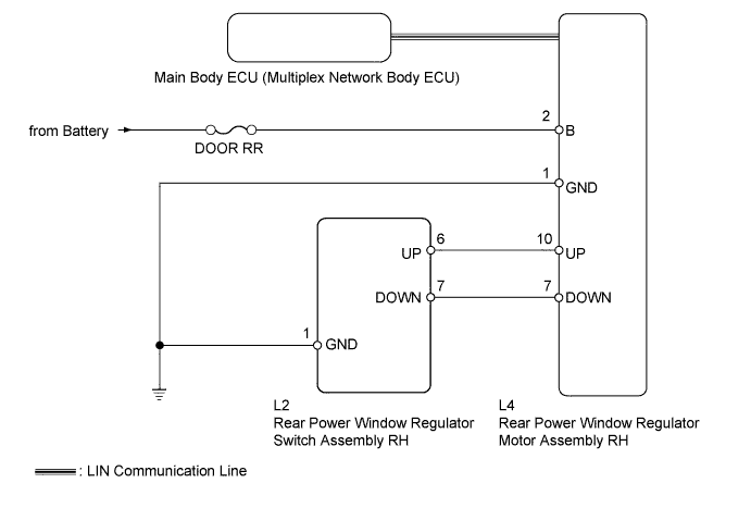
WIRING DIAGRAM
INSPECTION PROCEDURE
Note
Inspect the fuses for circuits related to this system before performing the following inspection procedure.
Tech Tips
Since the power window control system has functions that use LIN communication, first confirm that there is no malfunction in the communication system by inspecting the LIN communication functions in accordance with the "How to Proceed with Troubleshooting" procedures. Then, conduct the following inspection procedure.
PROCEDURE
-
CHECK FOR DTC (B2312)
-
Check if DTC B2312 is output Click here.
OK DTC B2312 is not output.
NG 
GO TO DTC B2312 Click here
OK 
-
-
READ VALUE USING INTELLIGENT TESTER (REAR POWER WINDOW REGULATOR SWITCH)
-
Use the Data List to check if the rear power window regulator motor is functioning properly Click here.
RR-Door Motor Tester Display Measurement Item/Range Normal Condition Diagnostic Note RR Door P/W Up SW Rear power window RH manual up signal / ON or OFF ON: Rear power window RH manual up switch operated
OFF: Rear power window RH switch not operated
- RR Door P/W Down SW Rear power window RH manual down signal / ON or OFF ON: Rear power window RH manual down switch operated
OFF: Rear power window RH switch not operated
- OK On tester screen, each item changes between ON and OFF according to above chart.
NG 
INSPECT REAR POWER WINDOW REGULATOR SWITCH ASSEMBLY RH Click here
OK
-
-
PERFORM ACTIVE TEST USING INTELLIGENT TESTER (POWER WINDOW)
-
Select the Active Test, use the intelligent tester to generate a control command, and then check that power window regulator motor operates Click here.
RR-Door Motor Tester Display Test Part Control Range Diagnostic Note Power Window Passenger side power window OFF/UP/DOWN - OK The power window regulator motor operates normally.
NG
REPLACE REAR POWER WINDOW REGULATOR MOTOR ASSEMBLY RH Click here
OK 
REPLACE MAIN BODY ECU (MULTIPLEX NETWORK BODY ECU) Click here
-
-
INSPECT REAR POWER WINDOW REGULATOR SWITCH ASSEMBLY RH
-
Remove the rear power window regulator switch Click here.
-
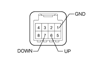
Measure the resistance according to the value(s) in the table below.
Standard Resistance Tester Connection Switch Condition Specified Condition 6 (UP) - 1 (GND) Manual up operation Below 1 Ω 7 (DOWN) - 1 (GND) Manual down operation Below 1 Ω 6 (UP) - 1 (GND) Not operated 10 kΩ or higher 7 (DOWN) - 1 (GND) Not operated 10 kΩ or higher
NG
REPLACE REAR POWER WINDOW REGULATOR SWITCH ASSEMBLY RH Click here
OK
-
-
CHECK HARNESS AND CONNECTOR (REAR POWER WINDOW REGULATOR SWITCH ASSEMBLY RH - BODY GROUND)
-
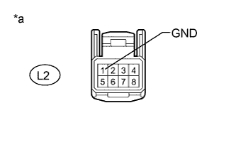
Text in Illustration *a Front view of wire harness connector
(to Rear Power Window Regulator Switch Assembly RH)
Disconnect the L2 rear power window regulator switch connector.
-
Measure the resistance according to the value(s) in the table below.
Standard Resistance Tester Connection Condition Specified Condition L2-1 (GND) - Body ground Always Below 1 Ω
NG
REPAIR OR REPLACE HARNESS OR CONNECTOR
OK
-
-
CHECK HARNESS AND CONNECTOR (REAR POWER WINDOW REGULATOR SWITCH ASSEMBLY RH - REAR POWER WINDOW REGULATOR MOTOR ASSEMBLY RH)
-
Disconnect the L2 rear power window regulator switch connector.
-
Disconnect the L4 rear power window regulator motor connector.
-
Measure the resistance according to the value(s) in the table below.
Standard Resistance Tester Connection Condition Specified Condition L2-6 (UP) - L4-10 (UP) Always Below 1 Ω L2-7 (DOWN) - L4-7 (DOWN) Always Below 1 Ω L2-6 (UP) - Body ground Always 10 kΩ or higher L2-7 (DOWN) - Body ground Always 10 kΩ or higher
NG
REPAIR OR REPLACE HARNESS OR CONNECTOR
OK
-
-
CHECK HARNESS AND CONNECTOR (REAR POWER WINDOW REGULATOR MOTOR ASSEMBLY RH - BATTERY AND BODY GROUND)
-
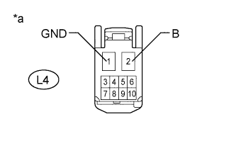
Text in Illustration *a Front view of wire harness connector
(to Rear Power Window Regulator Motor Assembly RH)
Disconnect the L4 rear power window regulator motor connector.
-
Measure the voltage according to the value(s) in the table below.
Standard Voltage Tester Connection Condition Specified Condition L4-2 (B) - Body ground Always 11 to 14 V -
Measure the resistance according to the value(s) in the table below.
Standard Resistance Tester Connection Condition Specified Condition L4-1 (GND) - Body ground Always Below 1 Ω
NG
REPAIR OR REPLACE HARNESS OR CONNECTOR
OK
REPLACE REAR POWER WINDOW REGULATOR MOTOR ASSEMBLY RH Click here
-