ROOF HEADLINING (for 3 Door) REASSEMBLY

Tech Tips
-
Use the same procedure for RHD and LHD vehicles.
-
The procedure listed below is for LHD vehicles.
-
INSTALL NO. 2 ANTENNA CORD SUB-ASSEMBLY
-
w/o Sliding Roof:
-
Apply new double-sided tape as shown in the illustration.
Tech Tips
Attach double-sided tape to the hatched areas shown in the illustration below.
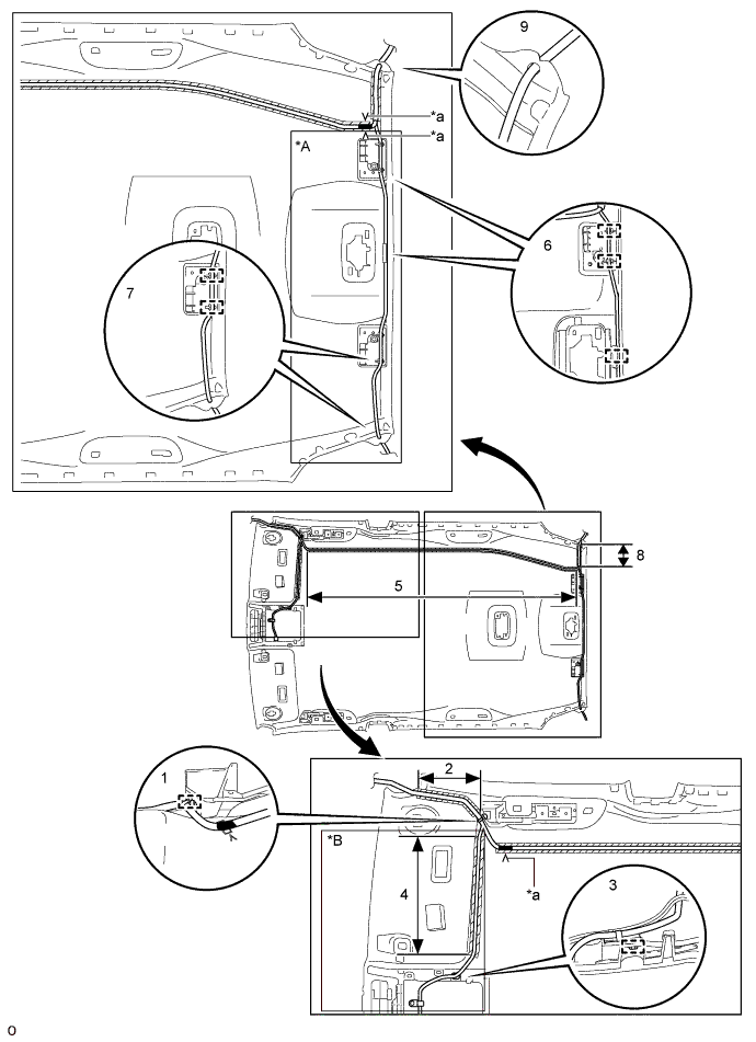
Text in Illustration *A for Diversity *B for Diversity, w/ Digital Audio Broadcasting *a V Mark - - 
Marking Tape 
Double-sided Tape -
Attach the clamp in the part of the illustration labeled 1.
-
Align the antenna cord with the marking in the part of the illustration labeled 2 and attach it to the double-sided tape.
-
Attach the clamp in the part of the illustration labeled 3.
-
Align the antenna cord with the marking in the part of the illustration labeled 4 and attach it to the double-sided tape.
-
Align the marking tape on the antenna cord with the V marks on the front and rear of the roof headlining, and then align the antenna cord with the marking in the part of the illustration labeled 5 and attach it to the double-sided tape.
-
Attach the clamps in the parts of the illustration labeled 6 and 7.
-
Align the antenna cord with the marking in the part of the illustration labeled 8 and attach it to the double-sided tape.
-
Attach the antenna cord to the notches in the roof headlining in the parts of the illustration labeled 7 and 9.
-
-
w/ Sliding Roof:
-
Apply new double-sided tape as shown in the illustration.
Tech Tips
Attach double-sided tape to the hatched areas shown in the illustration below.
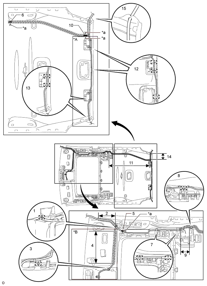
Text in Illustration *A for Diversity *B for Diversity, w/ Digital Audio Broadcasting *a V Mark - - Marking Tape Double-sided Tape -
Attach the clamp in the part of the illustration labeled 1.
-
Align the antenna cord with the marking in the part of the illustration labeled 2 and attach it to the double-sided tape.
-
Attach the clamp in the part of the illustration labeled 3.
-
Align the antenna cord with the marking in the part of the illustration labeled 4 and attach it to the double-sided tape.
-
Align the marking tape on the antenna cord with the V marks on the roof headlining in the part of the illustration labeled 5 and 6.
-
Attach the clamps in the part of the illustration labeled 7.
-
Attach the clamp in the part of the illustration labeled 8.
-
Align the antenna cord with the marking in the part of the illustration labeled 9 and attach it to the double-sided tape.
-
Align the marking tape on the antenna cord with the V marks on the roof headlining in the part of the illustration labeled 10.
-
While gathering the slack in the antenna cord in the part of the illustration labeled 11, align the antenna cord with the marking and attach it to the double-sided tape.
-
Attach the clamps in the parts of the illustration labeled 12 and 13.
-
Align the antenna cord with the marking in the part of the illustration labeled 14 and attach it to the double-sided tape.
-
Attach the antenna cord to the notches in the roof headlining in the parts of the illustration labeled 13 and 15.
-
-
-
INSTALL NO. 1 ROOF WIRE
-
Apply butyl tape to the roof headlining so that the tape is aligned with the wire harness marking as shown in the illustration.
Tech Tips
Use butyl tape that has a width of 10 mm (0.394 in.).
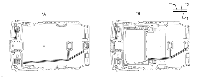
Text in Illustration *A w/o Sliding Roof *B w/ Sliding Roof *1 Wire Harness Marking *2 Butyl Tape -
Align the No. 1 roof wire with the wire harness installation points as shown in the illustration and attach it to the roof headlining to install it.
Tech Tips
Be sure to securely attach the roof wire so that it is not twisted.
-
Attach each clamp.
Tech Tips
Make sure the EC mirror wire harness (w/ EC Mirror) and rain sensor wire harness (w/ Rain Sensor) are securely set into the cutouts of the roof headlining.
-
Turn the visor connectors approximately 90° clockwise to install them to the roof headlining.
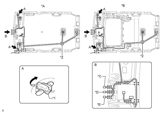
Text in Illustration *A w/o Sliding Roof *B w/ Sliding Roof *C w/ Rain Sensor, for LHD *D w/ EC Mirror *E w/ Rain Sensor, for RHD - - *1 Wire Harness Marking *2 Wire Harness Installation Point
-
-
INSTALL VANITY LIGHT ASSEMBLY LH
-
Attach the 3 claws to install the vanity light.
-
-
INSTALL VANITY LIGHT ASSEMBLY RH
Tech Tips
Use the same procedure described for the LH side.
-
INSTALL NO. 4 ROOF SILENCER PAD (w/o Sliding Roof)
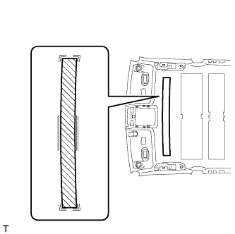
-
Align the No. 4 roof silencer pad with the markings on the roof headlining and install the No. 4 roof silencer pad to the position shown in the illustration using hot-melt glue or double-sided tape.
-
-
INSTALL NO. 2 ROOF SILENCER PAD (w/o Sliding Roof)
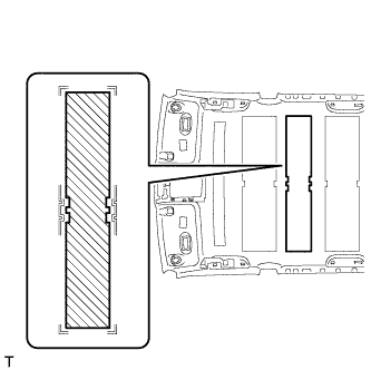
-
Align the No. 2 roof silencer pad with the markings on the roof headlining and install the No. 2 roof silencer pad to the position shown in the illustration using hot-melt glue or double-sided tape.
-
-
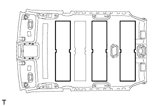
INSTALL NO. 1 ROOF SILENCER PAD
-
w/o Sliding Roof:
-
Align the 3 No. 1 roof silencer pads with the markings on the roof headlining and install the 3 No. 1 roof silencer pads to the position shown in the illustration using hot-melt glue or double-sided tape.
-
-
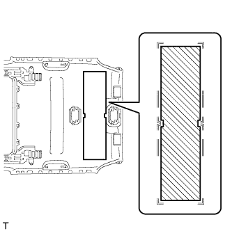
w/ Sliding Roof:
-
Align the No. 1 roof silencer pad with the markings on the roof headlining and install the No. 1 roof silencer pad to the position shown in the illustration using hot-melt glue or double-sided tape.
-
-