INSTRUMENT PANEL SAFETY PAD REASSEMBLY

Tech Tips
-
Use the same procedure for RHD and LHD vehicles.
-
The procedure listed below is for LHD vehicles.
-
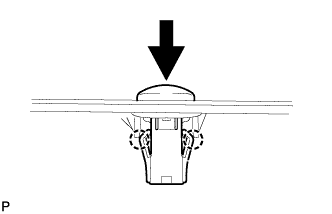
REMOVE SECURITY INDICATOR LIGHT ASSEMBLY
-
Attach the 2 claws to install the security indicator light.
-
Connect the connector.
-
-
REMOVE SUNSHINE SENSOR HOLE COVER (w/o Automatic Light Control System)
-
Attach the 2 claws to install the sunshine sensor hole cover.
-
-
INSTALL AUTOMATIC LIGHT CONTROL SENSOR (w/ Automatic Light Control System)
-
Attach the 2 claws to install the sensor.
-
Connect the connector.
-
-
INSTALL ENGINE SWITCH (w/ Entry and Start System)
-
Attach the 2 claws to install the engine switch.
-
Connect the connector.
-
-
INSTALL INSTRUMENT PANEL PASSENGER AIRBAG ASSEMBLY
-
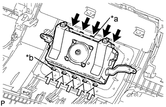
Text in Illustration *a Hook A *b Hook B Attach the 5 hooks (A).
-
Attach the 5 hooks (B) to install the instrument panel passenger airbag.
-
Install the 2 screws.
-
-
INSTALL NAVIGATION ANTENNA ASSEMBLY (w/ Navigation System)
-
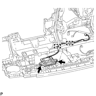
Install the navigation antenna assembly with the 2 screws.
-
Attach the 2 clamps.
-
-
INSTALL NO. 2 INSTRUMENT PANEL WIRE
-
for LHD:
-
Attach the 20 clamps to install the No. 2 instrument panel wire.
-
Connect the 2 connectors.
-
-
for RHD:
-
Attach the 20 clamps to install the No. 2 instrument panel wire.
-
Connect the 2 connectors.
-
-
-
INSTALL NO. 1 DEFROSTER NOZZLE GARNISH
-
Install the No. 1 defroster nozzle garnish with the 6 screws <A>.
-
-
INSTALL NO. 3 HEATER TO REGISTER DUCT
-
Install the No. 3 heater to register duct with the 2 screws <A>.
-
-
INSTALL DEFROSTER NOZZLE ASSEMBLY
-
Install the defroster nozzle with the 4 screws <A>.
-
-
INSTALL NO. 1 SIDE DEFROSTER NOZZLE DUCT
-
Attach the 2 claws to install the No. 1 side defroster nozzle duct.
-
Install the screw <A>.
-
-
INSTALL NO. 2 SIDE DEFROSTER NOZZLE DUCT
Tech Tips
Use the same procedure described for the No. 1 side defroster nozzle duct.
-
INSTALL NO. 1 HEATER TO REGISTER DUCT
-
Install the No. 1 heater to register duct with the 4 screws <A>.
-
-
INSTALL NO. 2 HEATER TO REGISTER DUCT
Tech Tips
Use the same procedure described for the No. 1 heater to register duct.