-
Use the same procedure for RHD and LHD vehicles.
-
The procedure listed below is for LHD vehicles.
- Click here
INSTALL NO. 2 ANTENNA CORD SUB-ASSEMBLY
-
w/o Sliding Roof:
-
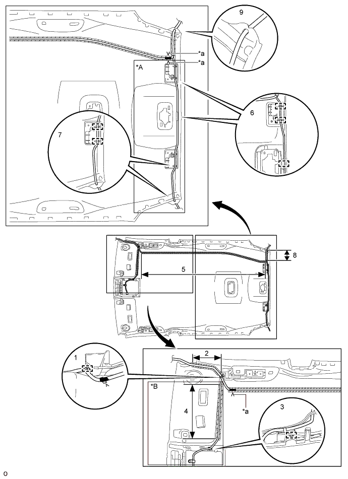
Apply new double-sided tape as shown in the illustration.
Tip:Attach double-sided tape to the hatched areas shown in the illustration below.
Table 1. Text in Illustration *A for Diversity *B for Diversity, w/ Digital Audio Broadcasting *a V Mark - - 
Marking Tape 
Double-sided Tape -
Attach the clamp in the part of the illustration labeled 1.
-
Align the antenna cord with the marking in the part of the illustration labeled 2 and attach it to the double-sided tape.
-
Attach the clamp in the part of the illustration labeled 3.
-
Align the antenna cord with the marking in the part of the illustration labeled 4 and attach it to the double-sided tape.
-
Align the marking tape on the antenna cord with the V marks on the front and rear of the roof headlining, and then align the antenna cord with the marking in the part of the illustration labeled 5 and attach it to the double-sided tape.
-
Attach the clamps in the parts of the illustration labeled 6 and 7.
-
Align the antenna cord with the marking in the part of the illustration labeled 8 and attach it to the double-sided tape.
-
Attach the antenna cord to the notches in the roof headlining in the parts of the illustration labeled 7 and 9.
-
-
w/ Sliding Roof:
-
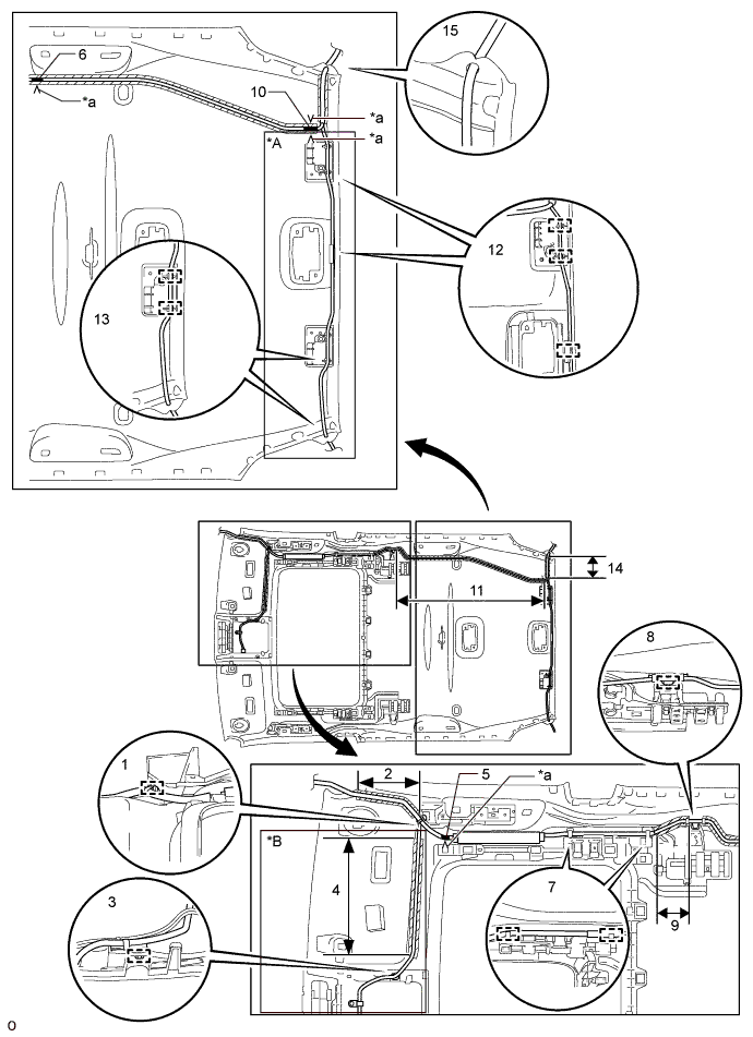
Apply new double-sided tape as shown in the illustration.
Tip:Attach double-sided tape to the hatched areas shown in the illustration below.
Table 2. Text in Illustration *A for Diversity *B for Diversity, w/ Digital Audio Broadcasting *a V Mark - - Marking Tape Double-sided Tape -
Attach the clamp in the part of the illustration labeled 1.
-
Align the antenna cord with the marking in the part of the illustration labeled 2 and attach it to the double-sided tape.
-
Attach the clamp in the part of the illustration labeled 3.
-
Align the antenna cord with the marking in the part of the illustration labeled 4 and attach it to the double-sided tape.
-
Align the marking tape on the antenna cord with the V marks on the roof headlining in the part of the illustration labeled 5 and 6.
-
Attach the clamps in the part of the illustration labeled 7.
-
Attach the clamp in the part of the illustration labeled 8.
-
Align the antenna cord with the marking in the part of the illustration labeled 9 and attach it to the double-sided tape.
-
Align the marking tape on the antenna cord with the V marks on the roof headlining in the part of the illustration labeled 10.
-
While gathering the slack in the antenna cord in the part of the illustration labeled 11, align the antenna cord with the marking and attach it to the double-sided tape.
-
Attach the clamps in the parts of the illustration labeled 12 and 13.
-
Align the antenna cord with the marking in the part of the illustration labeled 14 and attach it to the double-sided tape.
-
Attach the antenna cord to the notches in the roof headlining in the parts of the illustration labeled 13 and 15.
-
-
- Click here
INSTALL NO. 1 ROOF WIRE
-
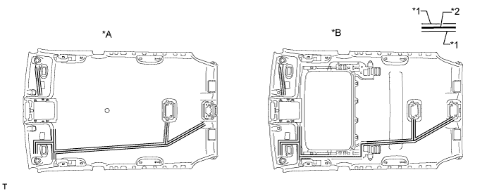
Apply butyl tape to the roof headlining so that the tape is aligned with the wire harness marking as shown in the illustration.
Tip:Use butyl tape that has a width of 10 mm (0.394 in.).
Table 3. Text in Illustration *A w/o Sliding Roof *B w/ Sliding Roof *1 Wire Harness Marking *2 Butyl Tape -
Align the No. 1 roof wire with the wire harness installation points as shown in the illustration and attach it to the roof headlining to install it.
Tip:Be sure to securely attach the roof wire so that it is not twisted.
-
Attach each clamp.
Tip:Make sure the EC mirror wire harness (w/ EC Mirror) and rain sensor wire harness (w/ Rain Sensor) are securely set into the cutouts of the roof headlining.
-
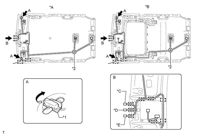
Turn the visor connectors approximately 90° clockwise to install them to the roof headlining.
Table 4. Text in Illustration *A w/o Sliding Roof *B w/ Sliding Roof *C w/ Rain Sensor, for LHD *D w/ EC Mirror *E w/ Rain Sensor, for RHD - - *1 Wire Harness Marking *2 Wire Harness Installation Point
-
- Click here
INSTALL VANITY LIGHT ASSEMBLY LH
-
Attach the 3 claws to install the vanity light.
-
- Click here
INSTALL VANITY LIGHT ASSEMBLY RH
Tip:Use the same procedure described for the LH side.
-
Click here
INSTALL NO. 4 ROOF SILENCER PAD (w/o Sliding Roof)
-
Align the No. 4 roof silencer pad with the markings on the roof headlining and install the No. 4 roof silencer pad to the position shown in the illustration using hot-melt glue or double-sided tape.
-
-
Click here
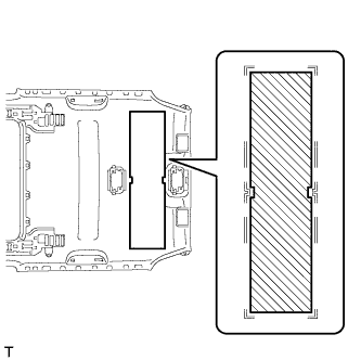
INSTALL NO. 2 ROOF SILENCER PAD (w/o Sliding Roof)
-
Align the No. 2 roof silencer pad with the markings on the roof headlining and install the No. 2 roof silencer pad to the position shown in the illustration using hot-melt glue or double-sided tape.
-
-
Click here
INSTALL NO. 1 ROOF SILENCER PAD
-
w/o Sliding Roof:
-
Align the 3 No. 1 roof silencer pads with the markings on the roof headlining and install the 3 No. 1 roof silencer pads to the position shown in the illustration using hot-melt glue or double-sided tape.
-
-
w/ Sliding Roof:
-
Align the No. 1 roof silencer pad with the markings on the roof headlining and install the No. 1 roof silencer pad to the position shown in the illustration using hot-melt glue or double-sided tape.
-
-