VOLTAGE INVERTER (for 5 Door) ON-VEHICLE INSPECTION

-
INSPECT VOLTAGE INVERTER ASSEMBLY
Tech Tips
Remove interior parts so that the voltage inverter can be seen.
-
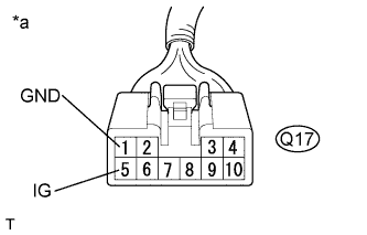
Text in Illustration *a Front view of wire harness connector
(to Voltage Inverter Assembly)
Disconnect the voltage inverter connector.
-
Measure the voltage according to the value(s) in the table below.
Standard Voltage Tester Connection Switch Condition Specified Condition Q17-5 (IG) - Q17-1 (GND) Ignition switch ON 11 to 14 V Q17-1 (GND) - Body ground Always Below 1 V If the result is not as specified, repair or replace the harness or connector.
-
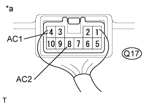
Text in Illustration *a Component with harness connected
(Voltage Inverter Assembly)
Reconnect the voltage inverter connector.
-
Measure the voltage according to the value(s) in the table below.
Standard Voltage Tester Connection Switch Condition Specified Condition Q17-4 (AC1) - Q17-8 (AC2) Ignition switch ON, main switch on AC 220 V If the result is not as specified, replace the voltage inverter assembly.
-