AIR CONDITIONING PANEL REASSEMBLY

Tech Tips
-
Use the same procedure for RHD and LHD vehicles.
-
The procedure listed below is for LHD vehicles.
-
INSTALL HEATER CONTROL HOUSING SUB-ASSEMBLY (except G.C.C.)
-
Align the axis of the heater control housing sub-assembly gear with the encoder hole and insert the gear.
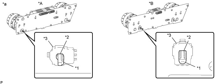
Text in Illustration *A for Automatic Air Conditioning System *B for Manual Air Conditioning System *1 Gear Axis *2 Encoder Hole *3 Metal Cover - - *a Procedure Necessary to Prevent Electrostatic Discharge - - Note
-
Do not touch any IC, circuit trace or circuit element without taking measures to prevent electrostatic discharge.
-
Insert the gear of the heater control housing sub-assembly perpendicular to the No. 1 center cluster module circuit sub-assembly.
-
The metal cover of the encoder can easily come off, so hold the cover in place while inserting the gear.
-
Do not place excessive force on the dials of the heater control housing sub-assembly.
-
Do not allow oil, grease or other foreign matter to contact the heater control housing sub-assembly and prevent it from being damaged.
-
After installing the heater control housing sub-assembly with the screws, remove the tape fixing the dials in place from the new heater control housing sub-assembly.
-
-
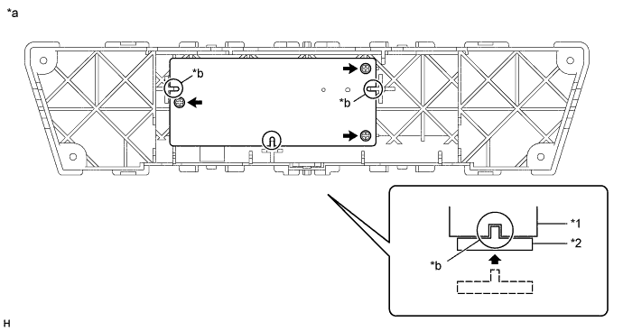
Check that the slit or hole of the gear and the hole of the housing are positioned as shown in the illustration.
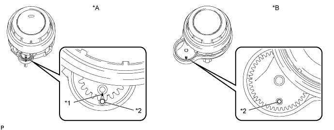
Text in Illustration *A for Automatic Air Conditioning System *B for Manual Air Conditioning System *1 Slit *2 Hole -
Align the positioning pins on the heater control housing sub-assembly with the holes on the circuit board of the No. 1 center cluster module circuit sub-assembly, and then install the heater control housing sub-assembly to the center cluster module circuit with the 2 screws.
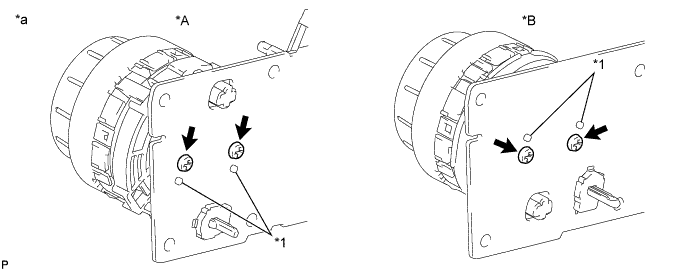
Text in Illustration *A for Automatic Air Conditioning System *B for Manual Air Conditioning System *1 Positioning Pin - - *a Procedure Necessary to Prevent Electrostatic Discharge - - Note
-
Be careful not to break the positioning pins on the heater control housing sub-assembly.
-
Be careful not to damage the circuit board of the No. 1 center cluster module circuit sub-assembly.
-
-
-
INSTALL CONTROL KNOB SUB-ASSEMBLY
-
for Automatic Air Conditioning System:
Install the control knob sub-assembly.
-
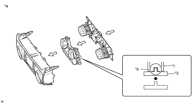
Install the control knob sub-assembly and No. 1 center cluster module circuit sub-assembly to the front air conditioning panel sub-assembly.
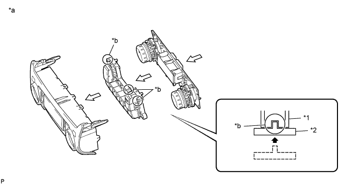
Text in Illustration *1 Front Air Conditioning Panel Sub-assembly *2 Control Knob Sub-assembly *a Procedure Necessary to Prevent Electrostatic Discharge *b Confirm Correct Engagement Tech Tips
Position the control knob sub-assembly so that the knobs face upwards and, while holding the front air conditioning panel sub-assembly parallel to the control knob sub-assembly, place the front air conditioning panel sub-assembly onto the control knob sub-assembly to install it.
Note
-
Be sure not to allow skin oils, grease, foreign matter, etc. to adhere to the parts and be sure not to damage the parts.
-
When installing the control knob sub-assembly and No. 1 center cluster module circuit sub-assembly to the front air conditioning panel sub-assembly, make sure that the ribs are properly engaged as shown in the illustration.
-
Do not apply excessive force to the knobs when installing the control knob sub-assembly as the knobs break easily.
-
Do not touch any IC, circuit trace or circuit element without taking measures to prevent electrostatic discharge.
-
-
Install the 6 screws.
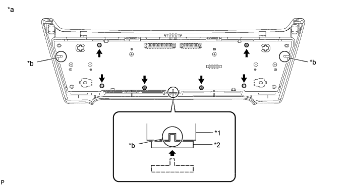
Text in Illustration *1 No. 1 Center Cluster Module Circuit Sub-assembly *2 Front Air Conditioning Panel Sub-assembly *a Procedure Necessary to Prevent Electrostatic Discharge *b Confirm Correct Engagement Note
-
Be sure not to allow skin oils, grease, foreign matter, etc. to adhere to the parts and be sure not to damage the parts.
-
Do not touch any IC, circuit trace or circuit element without taking measures to prevent electrostatic discharge.
-
Do not damage the No. 1 center cluster module circuit sub-assembly when tightening the screws.
-
-
-
for Manual Air Conditioning System:
Install the control knob sub-assembly.
-
Install the control knob sub-assembly and No. 1 center cluster module circuit sub-assembly to the front air conditioning panel sub-assembly.
Text in Illustration *1 Front Air Conditioning Panel Sub-assembly *2 Control Knob Sub-assembly *a Procedure Necessary to Prevent Electrostatic Discharge *b Confirm Correct Engagement Note
-
Be sure not to allow skin oils, grease, foreign matter, etc. to adhere to the parts and be sure not to damage the parts.
-
When installing the knob sub-assembly and No. 1 center cluster module circuit sub-assembly to the front case sub-assembly, make sure that the ribs are properly engaged as shown in the illustration.
-
Do not apply excessive force to the knobs when installing the knob sub-assembly as the knobs break easily.
-
Do not touch any IC, circuit trace or circuit element without taking measures to prevent electrostatic discharge.
-
-
Install the 6 screws.
Text in Illustration *1 No. 1 Center Cluster Module Circuit Sub-assembly *2 Front Air Conditioning Panel Sub-assembly *a Procedure Necessary to Prevent Electrostatic Discharge *b Confirm correct engagement Note
-
Be sure not to allow skin oils, grease, foreign matter, etc. to adhere to the parts and be sure not to damage the parts.
-
Do not touch any IC, circuit trace or circuit element without taking measures to prevent electrostatic discharge.
-
Do not damage the No. 1 center cluster module circuit sub-assembly when tightening the screws.
-
-
-
-
INSTALL NO. 2 CENTER CLUSTER MODULE CIRCUIT SUB-ASSEMBLY
-
Install the No. 2 center cluster module circuit sub-assembly to the rear air conditioning panel sub-assembly.
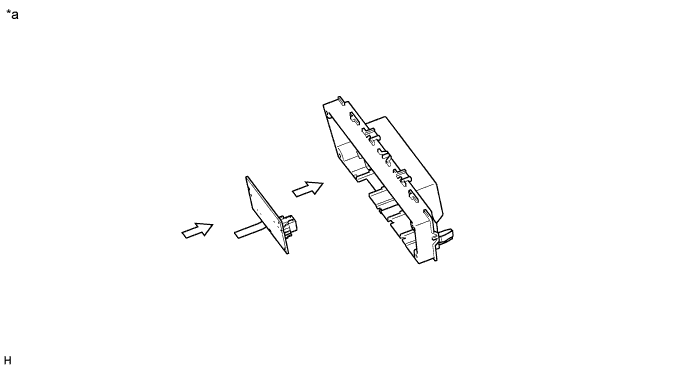
Text in Illustration *a Procedure Necessary to Prevent Electrostatic Discharge - - Note
-
When installing the No. 2 center cluster module circuit sub-assembly to the rear case sub-assembly, make sure that the ribs are properly engaged as shown in the illustration.
-
Do not touch any IC, circuit trace or circuit element without taking measures to prevent electrostatic discharge.
-
-
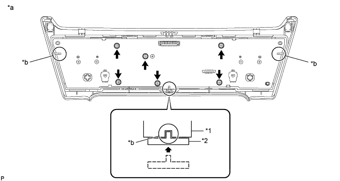
Install the 3 screws.
Text in Illustration *1 No. 2 Center Cluster Module Circuit Sub-assembly *2 Rear Air Conditioning Panel Sub-assembly *a Procedure Necessary to Prevent Electrostatic Discharge *b Confirm correct engagement Note
-
Do not touch any IC, circuit trace or circuit element without taking measures to prevent electrostatic discharge.
-
Do not damage the No. 2 center cluster module circuit sub-assembly when tightening the screws.
-
-
Pull back the lock of the connector to unlock it.
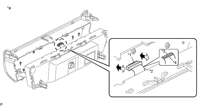
Text in Illustration *1 Connector *2 Flexible Ribbon Cable *3 Blue Tape *4 Black Line *a Procedure Necessary to Prevent Electrostatic Discharge - - 
Lock 
Unlock -
Connect the flexible ribbon cable, and then push in the lock to lock the connector.
Note
-
Make sure that the flexible ribbon cable is connected securely and the lock of the connector is locked securely.
-
Make sure that the black line on the flexible ribbon cable is not visible after locking the connector.
-
When disconnecting the connector, do not pull it with excessive force.
-
Do not pull the flexible ribbon cable after connecting it.
-
Do not touch any IC, circuit trace or circuit element without taking measures to prevent electrostatic discharge.
-
-
Attach the 4 claws to install the rear air conditioning panel sub-assembly together with the No. 2 center cluster module circuit sub-assembly to the front air conditioning panel sub-assembly.
Note
-
Make sure that the flexible ribbon cable does not get pinched between the front air conditioning panel and rear air conditioning panel when installing the rear air conditioning panel.
-
-
Install the 4 screws.
-