-
Use the same procedure for RHD and LHD vehicles.
-
The procedure listed below is for LHD vehicles.
- Click here
REMOVE NO. 2 CENTER CLUSTER MODULE CIRCUIT SUB-ASSEMBLY
-
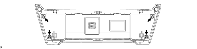
Remove the 4 screws.
-
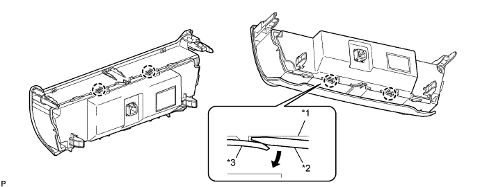
Using a screwdriver, detach the 4 claws as shown in the illustration.
Table 1. Text in Illustration *1 Rear Air Conditioning Panel Sub-assembly *2 Screwdriver *3 Front Air Conditioning Panel Sub-assembly - - Note:Do not pull the rear air conditioning panel sub-assembly as the flexible ribbon cable is connected to it.
-
Disconnect the connector and remove the rear air conditioning panel sub-assembly with the No. 2 center cluster module circuit sub-assembly.
-
Pull back the lock of the connector.
-
Disconnect the flexible ribbon cable.
-
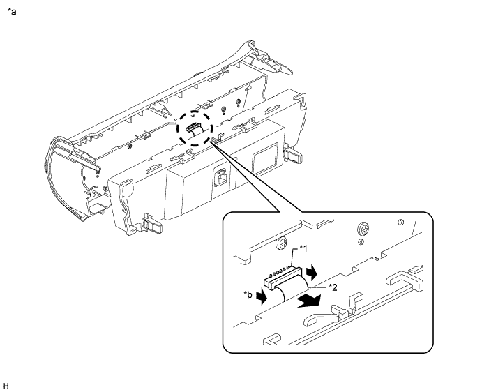
Remove the rear air conditioning panel sub-assembly together with the No. 2 center cluster module circuit sub-assembly.
Table 2. Text in Illustration *1 Connector *2 Flexible Ribbon Cable *a Procedure Necessary to Prevent Electrostatic Discharge *b Pull back lock Note:
-
Be sure to disconnect the flexible ribbon cable after pulling back the lock of the connector.
-
When disconnecting the connector, do not pull it with excessive force.
-
Do not pull the flexible ribbon cable when it is connected.
-
Do not touch any IC, circuit trace or circuit element without taking measures to prevent electrostatic discharge.
-
-
-
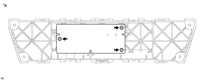
Remove the 3 screws.
Table 3. Text in Illustration *a Procedure Necessary to Prevent Electrostatic Discharge - - Note:
-
Do not touch any IC, circuit trace or circuit element without taking measures to prevent electrostatic discharge.
-
-
Remove the No. 2 center cluster module circuit sub-assembly from the rear air conditioning panel sub-assembly.
Note:
-
Do not pull the flexible ribbon cable.
-
Do not touch any IC, circuit trace or circuit element without taking measures to prevent electrostatic discharge.
-
-
- Click here
REMOVE CONTROL KNOB SUB-ASSEMBLY
-
for Automatic Air Conditioning System:
Remove the control knob sub-assembly.
-
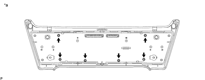
Remove the 6 screws.
Table 4. Text in Illustration *a Procedure Necessary to Prevent Electrostatic Discharge - - Note:
-
Do not remove any screws except for the 6 indicated by arrows in the illustration.
-
Be sure not to allow skin oils, grease, foreign matter, etc. to adhere to the LCD and be sure not to damage the LCD.
-
Do not touch any IC, circuit trace or circuit element without taking measures to prevent electrostatic discharge.
-
-
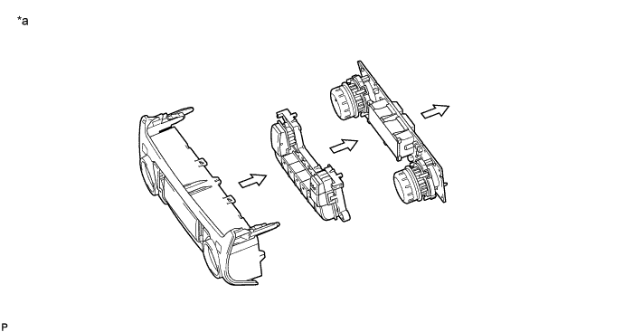
Remove the No. 1 center cluster module circuit sub-assembly and control knob sub-assembly from the front air conditioning panel sub-assembly.
Table 5. Text in Illustration *a Procedure Necessary to Prevent Electrostatic Discharge - - Note:
-
Be sure not to allow skin oils, grease, foreign matter, etc. to adhere to the LCD and be sure not to damage the LCD.
-
Do not apply excessive force to the knobs when removing the knob sub-assembly as the knobs break easily.
-
Do not touch any IC, circuit trace or circuit element without taking measures to prevent electrostatic discharge.
-
-
-
for Manual Air Conditioning System:
Remove the control knob sub-assembly.
-
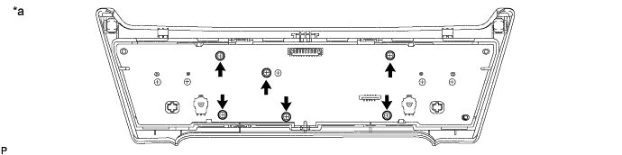
Remove the 6 screws.
Table 6. Text in Illustration *a Procedure Necessary to Prevent Electrostatic Discharge - - Note:
-
Do not remove any screws except for the 6 indicated by arrows in the illustration.
-
Be sure not to allow skin oils, grease, foreign matter, etc. to adhere to the LCD and be sure not to damage the LCD.
-
Do not touch any IC, circuit trace or circuit element without taking measures to prevent electrostatic discharge.
-
-
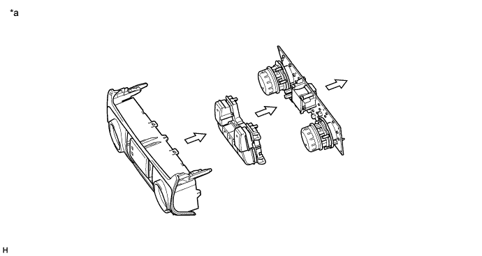
Remove the No. 1 center cluster module circuit sub-assembly and the control knob sub-assembly from the front air conditioning panel sub-assembly.
Table 7. Text in Illustration *a Procedure Necessary to Prevent Electrostatic Discharge - - Note:
-
Be sure not to allow skin oils, grease, foreign matter, etc. to adhere to the LCD and be sure not to damage the LCD.
-
Do not apply excessive force to the knobs when removing the knob sub-assembly as the knobs break easily.
-
Do not touch any IC, circuit trace or circuit element without taking measures to prevent electrostatic discharge.
-
-
-
- Click here
REMOVE HEATER CONTROL HOUSING SUB-ASSEMBLY (except G.C.C.)
-
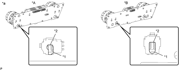
Turn the dial knob on the heater control housing sub-assembly to align the axis of the gear with the encoder hole as shown in the illustration.
Table 8. Text in Illustration *A for Automatic Air Conditioning System *B for Manual Air Conditioning System *1 Gear Axis *2 Encoder Hole *a Procedure Necessary to Prevent Electrostatic Discharge - - Note:Do not apply force to the axis of the gear.
-
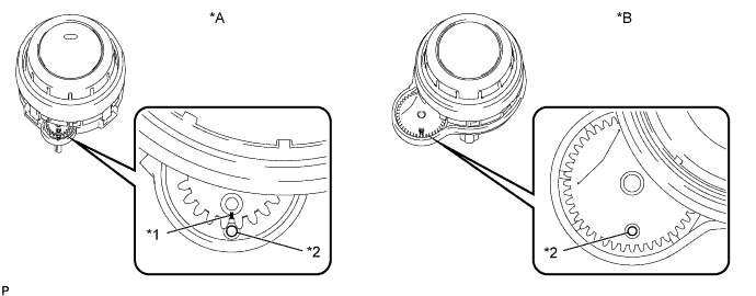
Check that the slit or hole of the gear and the hole of the housing are positioned as shown in the illustration.
Table 9. Text in Illustration *A for Automatic Air Conditioning System *B for Manual Air Conditioning System *1 Slit *2 Hole -
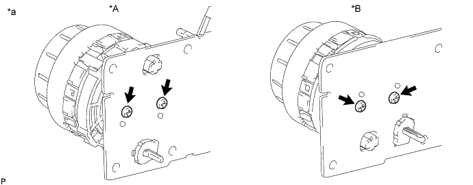
Remove the 2 screws and heater control housing sub-assembly from the center cluster module circuit.
Table 10. Text in Illustration *A for Automatic Air Conditioning System *B for Manual Air Conditioning System *a Procedure Necessary to Prevent Electrostatic Discharge - - Tip:Use the same procedure for the right side heater control housing sub-assembly.
Note:
-
Do not touch any IC, circuit trace or circuit element without taking measures to prevent electrostatic discharge.
-
Only remove the screws that are holding the heater control housing sub-assembly in place.
-
Do not mix the screws with other screws.
-
Do not allow oil, grease or other foreign matter to contact the heater control housing sub-assembly and prevent it from being damaged.
-
-