POWER OUTLET SOCKET (for Front) REMOVAL

-
REMOVE INTEGRATION CONTROL AND PANEL ASSEMBLY
-
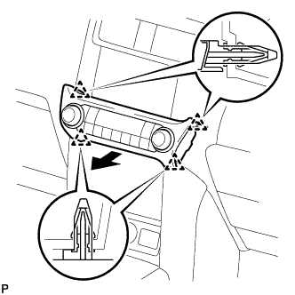
Detach the 4 clips.
-
Disconnect the connector and remove the integration control and panel assembly.
-
-
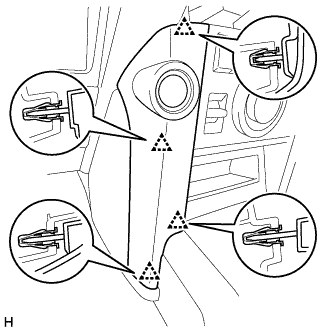
REMOVE INSTRUMENT PANEL FINISH PANEL END LH
-
Detach the 4 clips and remove the instrument panel finish panel end LH.
-
-
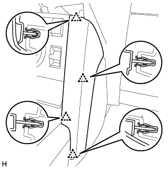
REMOVE INSTRUMENT PANEL FINISH PANEL END RH
-
Detach the 4 clips and remove the instrument panel finish panel end RH.
-
-
REMOVE FRONT CONSOLE UPPER PANEL GARNISH
-
w/o Seat Heater System:
-
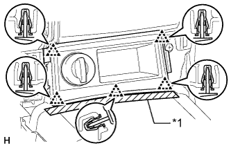
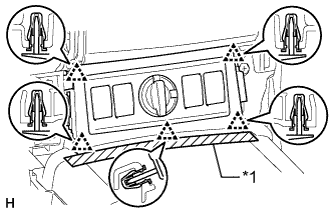
Text in Illustration *1 Protective Tape Put protective tape around the front console upper panel garnish.
-
Detach the 5 clips and remove the front console upper panel garnish.
-
Disconnect the connector.
-
-
w/o CRAWL:
-
Text in Illustration *1 Protective Tape Put protective tape around the front console upper panel garnish.
-
Detach the 5 clips and remove the front console upper panel garnish.
-
Disconnect each connector.
-
-
w/ CRAWL:
-
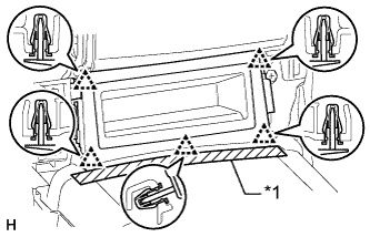
Text in Illustration *1 Protective Tape Put protective tape around the front console upper panel garnish.
-
Detach the 5 clips and remove the front console upper panel garnish.
-
-
-
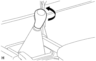
REMOVE SHIFT LEVER KNOB SUB-ASSEMBLY (for Automatic Transmission)
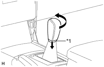
Text in Illustration *1 Shifting Hole Cover
-
Move the shifting hole cover downward.
-
Twist the shift lever knob in the direction indicated by the arrow and remove it.
-
-
REMOVE CONSOLE PANEL SUB-ASSEMBLY (for Automatic Transmission)
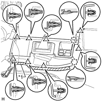
Text in Illustration *1 Protective Tape
-
Put protective tape around the console panel.
-
Using a moulding remover, detach the 8 clips and 2 claws.
-
Disconnect each connector and remove the console panel.
-
-
REMOVE SHIFT LEVER KNOB SUB-ASSEMBLY (for Manual Transmission)
-
Twist the shift lever knob in the direction indicated by the arrow and remove it.
-
-
REMOVE CONSOLE PANEL SUB-ASSEMBLY (for Manual Transmission)
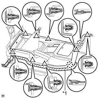
Text in Illustration *1 Protective Tape
-
Put protective tape around the console panel.
-
Using a moulding remover, detach the 8 clips and 2 claws.
-
Disconnect each connector and remove the console panel.
-
-
REMOVE POWER OUTLET SOCKET ASSEMBLY
-
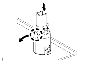
While pulling the claw of the power point socket in the direction of the arrow, push the power point socket toward the inside of the chamber to remove it.
-
-
REMOVE POWER OUTLET SOCKET COVER
-
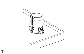
Detach the 2 claws and remove the socket cover.
-