REAR AIR CONDITIONING UNIT INSTALLATION

-
INSTALL REAR ROOF NO. 1 AIR DUCT
-
Install the duct with the 4 clips.
-
-
INSTALL REAR ROOF NO. 2 AIR DUCT
-
Install the duct with the clip.
-
-
INSTALL REAR ROOF NO. 3 AIR DUCT
-
Install the duct with the clip.
-
-
INSTALL REAR ROOF NO. 4 AIR DUCT
-
Install the duct with the clip.
-
-
INSTALL REAR ROOF NO. 5 AIR DUCT
-
Install the duct with the clip.
-
-
INSTALL REAR COOLING UNIT ASSEMBLY
-
Install the rear cooling unit to the vehicle with the 5 bolts.
- Torque:
- 5.4 N*m { 55 kgf*cm, 48 in.*lbf }
-
Connect the 3 connectors.
-
Attach the 3 clamps.
-
-
INSTALL REAR ROOF NO. 1 AIR DUCT
-
Insert the upper part of the duct into the roof side duct and, using that point as a pivot point, swing the duct into place and install it to the rear cooling unit.
-
Attach the 2 claws to install the cooler plate.
-
-
INSTALL REAR SIDE NO. 3 AIR DUCT
-
Install the duct with the 2 clips.
-
-
INSTALL REAR SIDE NO. 2 AIR DUCT
-
Install the duct with the 2 clips and attach the clamp.
-
-
INSTALL CURTAIN SHIELD AIRBAG ASSEMBLY RH
-
Install the curtain shield airbag with the 17 new bolts.
- Torque:
- 9.8 N*m { 100 kgf*cm, 87 in.*lbf }
Note
Do not twist the curtain shield airbag when installing it.
-
Connect the connector.
Note
When handling the airbag connector, take care not to damage the airbag wire harness.
-
-
CONNECT AIR CONDITIONER TUBE AND ACCESSORY ASSEMBLY
-
Remove the attached vinyl tape from the pipe.
-
Sufficiently apply compressor oil to 2 new O-rings and the fitting surface of the air conditioning tube and accessory assembly.
-
Install the 2 O-rings to the air conditioning tube and accessory assembly.
-
Connect the air conditioning tube and accessory assembly.
-
Install the bolt.
- Torque:
- 5.4 N*m { 55 kgf*cm, 48 in.*lbf }
-
Connect the heater water inlet hose and heater water outlet hose.
-
Using pliers, grip the claws of the clips and slide the 2 clips.
-
-
INSTALL REAR QUARTER TRIM PANEL ASSEMBLY RH
Tech Tips
Use the same procedure described for the LH side.
-
INSTALL DECK TRIM SIDE PANEL ASSEMBLY RH
-
w/o Rear No. 2 Seat:
-
Connect each connector.
-
Pass the rear seatback lock control lever base through the deck trim side panel.
-
Attach the 5 clips and 8 claws to install the deck trim side panel.
-
Install the 4 bolts and screw.
-
Attach the 6 claws and 2 guides to install the rear seatback lock control lever base to the deck trim side panel.
-
Install the rear No. 1 seat outer belt floor anchor with the bolt.
- Torque:
- 42 N*m { 428 kgf*cm, 31 ft.*lbf }
-
-
w/ Rear No. 2 Seat:
-
Connect each connector.
-
Attach the 4 clips and 8 claws to install the deck trim side panel.
-
Install the 2 bolts and screw.
-
Install the rear No. 2 seat outer belt floor anchor with the bolt.
- Torque:
- 42 N*m { 428 kgf*cm, 31 ft.*lbf }
-
Install the rear No. 1 seat outer belt floor anchor with the bolt.
- Torque:
- 42 N*m { 428 kgf*cm, 31 ft.*lbf }
-
-
-
INSTALL ASSIST GRIP SUB-ASSEMBLY (w/ Rear No. 2 Seat)
Tech Tips
Use the same procedure for the other assist grip.
-
Install the assist grip with the 2 bolts.
-
-
INSTALL ASSIST GRIP PLUG (w/ Rear No. 2 Seat)
Tech Tips
Use the same procedure for all assist grip plugs.
-
Attach the 2 claws to install the assist grip plug.
-
-
INSTALL FRONT DECK SIDE TRIM COVER RH (w/ Tonneau Cover)
Tech Tips
Use the same procedure for the other front deck side trim cover.
-
Attach the 2 claws to install the front deck side trim cover
-
-
INSTALL NO. 1 TONNEAU COVER HOLDER CAP (w/o Tonneau Cover)
Tech Tips
Use the same procedure for the other No. 1 tonneau cover holder cap.
-
Attach the 2 claws to install the No. 1 tonneau cover holder cap.
-
-
INSTALL NO. 1 LUGGAGE COMPARTMENT TRIM HOOK
Tech Tips
Use the same procedure for the other No. 1 luggage compartment trim hook.
-
Install the No. 1 luggage compartment trim hook by turning it clockwise.
-
-
INSTALL REAR NO. 1 LAP BELT OUTER ANCHOR COVER SEAT
Tech Tips
Use the same procedure for the other rear No. 1 seat outer lap belt anchor cover.
-
Attach the 3 claws to install the rear No. 1 seat outer lap belt anchor cover.
-
-
INSTALL REAR FLOOR CARPET ASSEMBLY (w/o Rear No. 2 Seat)
-
Attach the 4 claws to install the rear floor carpet.
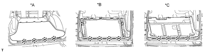
Text in Illustration *A w/o Deck Rail *B w/ Deck Rail *C for Face to Face Seat Type - -
-
-
INSTALL FLOOR SIDE RAIL RH (w/ Deck Rail)
Tech Tips
Use the same procedure described for the LH side.
-
INSTALL FLOOR SIDE RAIL LH (w/ Deck Rail)
-
Install the floor side rail with the 3 bolts.
-
-
INSTALL REAR FLOOR MAT REAR SUPPORT PLATE (w/o Rear No. 2 Seat)
-
Attach the 5 clips and 4 claws to install the rear floor mat rear support plate.
-
-
INSTALL NO. 1 DECK BOARD SUB-ASSEMBLY (w/o Rear No. 2 Seat)
-
Attach the clip to install the No. 1 deck board.
-
-
INSTALL FRONT LUGGAGE COMPARTMENT TRIM COVER (w/o Rear No. 2 Seat)
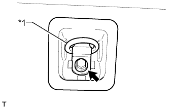
Text in Illustration *1 Luggage Hold Belt Striker Tech Tips
Use the same procedure for the other front luggage compartment trim cover.
-
Install the luggage hold belt striker and front luggage compartment trim cover with the bolt.
-
Attach the 4 claws to install the cap.
-
-
INSTALL TONNEAU COVER ASSEMBLY (w/ Tonneau Cover)
-
Install the tonneau cover.
-
-
INSTALL OUTER LAP BELT ANCHOR COVER
Tech Tips
Use the same procedure for the other outer lap belt anchor cover.
-
Attach the 3 claws to install the outer lap belt anchor cover
-
-
INSTALL REAR DOOR OPENING TRIM WEATHERSTRIP RH
Tech Tips
Use the same procedure described for the LH side.
-
INSTALL REAR DOOR SCUFF PLATE RH
Tech Tips
Use the same procedure described for the LH side.
-
INSTALL QUARTER SCUFF PLATE RH (w/ Rear No. 2 Seat)
Tech Tips
Use the same procedure described for the LH side.
-
INSTALL NO. 1 REAR FLOOR STEP COVER (w/ Rear No. 2 Seat)
-
for 60/40 Split Double-folding Seat Type LH Side:
Install the rear No. 1 seatback assembly Click here.
-
for 60/40 Split Double-folding Seat Type RH Side:
Install the rear No. 1 seatback assembly Click here.
-
-
INSTALL REAR NO. 1 SEATBACK ASSEMBLY
-
for 60/40 Split Double-folding Seat Type LH Side:
Install the rear No. 1 seatback assembly Click here.
-
for 60/40 Split Double-folding Seat Type RH Side:
Install the rear No. 1 seatback assembly Click here.
-
-
INSTALL REAR NO. 2 SEAT ASSEMBLY
-
for Manual Seat:
Install the rear No. 2 seat assembly Click here.
-
for Power Seat:
Install the rear No. 2 seat assembly Click here.
-
for Face to Face Seat Type:
Install the rear No. 2 seat assembly Click here.
-
-
CONNECT CABLE TO NEGATIVE BATTERY TERMINAL
Note
When disconnecting the cable, some systems need to be initialized after the cable is reconnected Click here.
-
ADD ENGINE COOLANT
-
for 1GR-FE:
Add engine coolant Click here.
-
for 2TR-FE:
Add engine coolant Click here.
-
for 1KD-FTV:
Add engine coolant Click here.
-
for 5L-E:
Add engine coolant Click here.
-
-
CHARGE REFRIGERANT
- SST
- 09985-20010 ( 09985-02130, 09985-02150, 09985-02090, 09985-02110, 09985-02010, 09985-02050, 09985-02060, 09985-02070 )
-
Perform vacuum purging using a vacuum pump.
-
Charge refrigerant HFC-134a (R134a).
Standard Model Code Air Conditioning Type Cool Box Refrigerant Charging Amount Except the model codes below w/o Rear Cooler w/ Cool Box 600 +/-30 g (21.2 +/-1.1 oz.) w/o Cool Box 550 +/-30 g (19.3 +/-1.1 oz.) w/ Rear Cooler w/ Cool Box 800 +/-30 g (28.2 +/-1.1 oz.) w/o Cool Box 770 +/-30 g (27.2 +/-1.1 oz.) w/ Rear Cooler
for Cold Area Specification Vehicles
w/o Cool Box 720 +/-30 g (25.3 +/-1.1 oz.) TRJ150L-GKMEKV
TRJ150L-GKPEKV
TRJ155L-GJPEKV
GRJ150L-GKFEKV
GRJ150L-GKAEKV
KDJ150L-GKFEYV
KDJ150L-GKAEYV
w/o Rear Cooler w/ Cool Box 600 +/-30 g (21.2 +/-1.1 oz.) w/o Cool Box 550 +/-30 g (19.3 +/-1.1 oz.) or 600 +/-30 g (21.2 +/-1.1 oz.) *1 w/ Rear Cooler w/ Cool Box 800 +/-30 g (28.2 +/-1.1 oz.) w/o Cool Box 770 +/-30 g (27.2 +/-1.1 oz.) *1: For vehicles with the 2TR-FE engine which have neither the rear cooler nor cool box, the refrigerant charging amount changes based on region.
Note
-
Do not operate the cooler compressor before charging refrigerant as the cooler compressor will not work properly without any refrigerant, and will overheat.
-
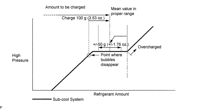
Approximately 100 g (3.53 oz.) of refrigerant may need to be charged after bubbles disappear. The refrigerant amount should be checked by measuring its quantity, and not with the sight glass.
-
-
WARM UP ENGINE
-
Warm up the engine at less than 1850 rpm for 2 minutes or more after charging the refrigerant.
Note
Be sure to warm up the compressor when turning the A/C switch is on after removing and installing the cooler refrigerant lines (including the compressor), to prevent damage to the compressor.
-
-
INSPECT FOR ENGINE COOLANT LEAKS
-
for 1GR-FE:
Check for engine coolant leaks Click here.
-
for 2TR-FE:
Check for engine coolant leaks Click here.
-
for 1KD-FTV:
Check for engine coolant leaks Click here.
-
for 5L-E:
Check for engine coolant leaks Click here.
-
-
CHECK FOR REFRIGERANT GAS LEAK
-
After recharging the refrigerant gas, check for refrigerant gas leakage using a halogen leak detector.
-
Perform the operation under these conditions:
-
Stop the engine.
-
Secure good ventilation (the halogen leak detector may react to volatile gases other than refrigerant, such as evaporated gasoline or exhaust gas).
-
Repeat the test 2 or 3 times.
-
Make sure that some refrigerant remains in the refrigeration system. When compressor is off: approximately 392 to 588 kPa (4.0 to 6.0 kgf/cm2, 57 to 85 psi).
-
-
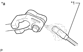
Text in Illustration *1 Halogen Leak Detector *a Check for Leakage Using a halogen leak detector, check the refrigerant line for leakage.
-
If a gas leak is not detected on the drain hose, remove the blower motor control (blower resistor) from the cooling unit. Insert the halogen leak detector sensor into the unit and perform the test.
-
Disconnect the connector and wait for approximately 20 minutes. Bring the halogen leak detector close to the pressure switch and perform the test.
-
-
CHECK SRS WARNING LIGHT
-
Check the SRS warning light Click here.
-
-
INSTALL UPPER RADIATOR SUPPORT SEAL
-
Install the upper radiator support seal with the 13 clips.
-