AIR CONDITIONING SYSTEM (for Manual Air Conditioning System) Viscous Heater with Magnet Clutch Circuit
DESCRIPTION
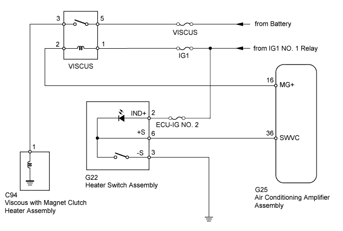
When the heater switch assembly is pushed, the air conditioning amplifier assembly turns on the viscous heater relay and operates the viscous heater. If the viscous heater does not operate when the heater switch assembly is pushed, there may be a problem in the circuit shown below.
WIRING DIAGRAM
INSPECTION PROCEDURE
Note
Inspect the fuses for circuits related to this system before performing the following inspection procedure.
PROCEDURE
-
READ VALUE USING INTELLIGENT TESTER (HEATER SWITCH)
-
Use the Data List to check if the heater switch assembly is functioning properly Click here.
Air Conditioner Tester Display Measurement Item/Range Normal Condition Diagnostic Note IDLE UP/PWR HEAT Switch Heater switch assembly / ON or OFF ON: Heater switch assembly on
OFF: Heater switch assembly off
- OK The display is as specified in the normal condition column.
NG 
INSPECT HEATER SWITCH ASSEMBLY Click here
OK 
PROCEED TO NEXT SUSPECTED AREA SHOWN IN PROBLEM SYMPTOMS TABLE Click here
-
-
INSPECT HEATER SWITCH ASSEMBLY
-
Remove the heater switch assembly Click here.
-
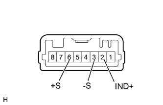
Measure the resistance according to the value(s) in the table below.
Standard Resistance Tester Connection Switch Condition Specified Condition 6 (+S) - 3 (-S) Heater switch assembly on Below 1 Ω 6 (+S) - 3 (-S) Heater switch assembly off 10 kΩ or higher -
Apply battery voltage to the heater switch assembly connector and check that the heater switch assembly illuminates.
OK Measurement Condition Specified Condition Battery positive (+) → Terminal 2 (IND+)
Battery negative (-) → Terminal 6 (+S)
LED illuminates
NG 
REPLACE HEATER SWITCH ASSEMBLY Click here
OK 
-
-
CHECK HARNESS AND CONNECTOR (HEATER SWITCH - AIR CONDITIONING AMPLIFIER)
-
Disconnect the G22 switch connector.
-
Disconnect the G25 amplifier connector.
-
Measure the resistance according to the value(s) in the table below.
Standard Resistance Tester Connection Condition Specified Condition G22-6 (+S) - G25-36 (SWVC) Always Below 1 Ω G22-6 (+S) - Body ground Always 10 kΩ or higher
NG
REPAIR OR REPLACE HARNESS OR CONNECTOR
OK
-
-
CHECK HARNESS AND CONNECTOR (HEATER SWITCH - BATTERY AND BODY GROUND)
-
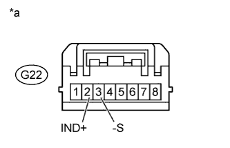
Text in Illustration *a Front view of wire harness connector
(to Heater Switch Assembly)
Disconnect the G22 switch connector.
-
Measure the voltage according to the value(s) in the table below.
Standard Voltage Tester Connection Switch Condition Specified Condition G22-2 (IND+) - Body ground Ignition switch ON 11 to 14 V -
Measure the resistance according to the value(s) in the table below.
Standard Resistance Tester Connection Condition Specified Condition G22-3 (-S) - Body ground Always Below 1 Ω
NG
REPAIR OR REPLACE HARNESS OR CONNECTOR
OK
-
-
CHECK HARNESS AND CONNECTOR (ENGINE ROOM NO. 1 RELAY BLOCK, JUNCTION BLOCK - BATTERY)
-
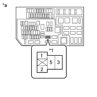
Text in Illustration *1 VISCUS Relay *a Component without relay installed
(Engine Room No. 1 Relay Block, Junction Block)
Remove the VISCUS relay from the engine room No. 1 relay block, junction block.
-
Measure the voltage according to the value(s) in the table below.
Standard Voltage Tester Connection Condition Specified Condition VISCUS relay terminal 5 - Body ground Ignition switch ON 11 to 14 V VISCUS relay terminal 2 - Body ground Always 11 to 14 V
NG
REPAIR OR REPLACE HARNESS OR CONNECTOR
OK
-
-
INSPECT VISCOUS HEATER RELAY (VISCUS)
-
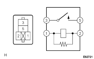
Remove the VISCUS relay from the engine room No. 1 relay block, junction block.
-
Measure the resistance according to the value(s) in the table below.
Standard Resistance Tester Connection Condition Specified Condition 3 - 5 Battery voltage is not applied to terminals 1 and 2 10 kΩ or higher Battery voltage is applied to terminals 1 and 2 Below 1 Ω
NG
REPLACE VISCOUS HEATER RELAY (VISCUS)
OK
-
-
CHECK HARNESS AND CONNECTOR (ENGINE ROOM NO. 1 RELAY BLOCK, JUNCTION BLOCK - VISCOUS WITH MAGNET CLUTCH HEATER)
-
Remove the VISCUS relay from the engine room No. 1 relay block, junction block.
-
Disconnect the C94 heater connector.
-
Measure the resistance according to the value(s) in the table below.
Standard Resistance Tester Connection Condition Specified Condition VISCUS relay terminal 3 - C94-1 Always Below 1 Ω VISCUS relay terminal 3 - Body ground Always 10 kΩ or higher
NG
REPAIR OR REPLACE HARNESS OR CONNECTOR
OK
-
-
CHECK HARNESS AND CONNECTOR (ENGINE ROOM NO. 1 RELAY BLOCK, JUNCTION BLOCK - AIR CONDITIONING AMPLIFIER)
-
Remove the VISCUS relay from the engine room No. 1 relay block, junction block.
-
Disconnect the G25 amplifier connector.
-
Measure the resistance according to the value(s) in the table below.
Standard Resistance Tester Connection Condition Specified Condition VISCUS relay terminal 2 - G25-16 (MG+) Always Below 1 Ω VISCUS relay terminal 2 - Body ground Always 10 kΩ or higher
NG
REPAIR OR REPLACE HARNESS OR CONNECTOR
OK
-
-
INSPECT VISCOUS WITH MAGNET CLUTCH HEATER ASSEMBLY
-

Remove the viscous with magnet clutch heater assembly Click here.
-
Apply battery voltage to the viscous with magnet clutch heater assembly and check the operation of the viscous with magnet clutch heater assembly.
OK Measurement Condition Specified Condition Battery positive (+) → Terminal 1
Battery negative (-) → Body ground
Viscous with magnet clutch heater assembly operating sound can be heard, and magnetic clutch hub and rotor lock.
NG
REPLACE VISCOUS WITH MAGNET CLUTCH HEATER ASSEMBLY Click here
OK
REPLACE AIR CONDITIONING AMPLIFIER ASSEMBLY Click here
-