AIR CONDITIONING SYSTEM (for Automatic Air Conditioning System), Diagnostic DTC:B1497/97

| DTC Code | DTC Name |
|---|---|
| B1497/97 | BUS IC Communication Malfunction |
DESCRIPTION
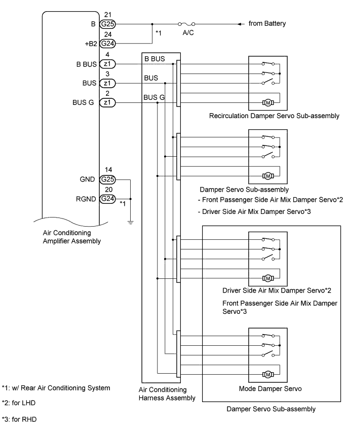
The air conditioning harness assembly connects the air conditioning amplifier assembly and each servo motor. The air conditioning amplifier assembly supplies power and sends operation instructions to each servo motor through the air conditioning harness assembly. Each servo motor sends the damper position information to the air conditioning amplifier assembly.
| DTC Code | DTC Detection Condition | Trouble Area |
|---|---|---|
| B1497/97 | An open circuit or malfunction in the communication line. |
|
-
*: w/ Rear Air Conditioning System
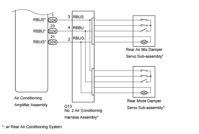
WIRING DIAGRAM
INSPECTION PROCEDURE
Note
Inspect the fuses for circuits related to this system before performing the following inspection procedure.
PROCEDURE
-
CHECK HARNESS AND CONNECTOR (POWER SOURCE)
*: w/ Rear Air Conditioning System
-
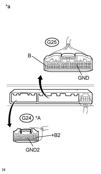
Text in Illustration *A w/ Rear Air Conditioning System *a Front view of wire harness connector
(to Air Conditioning Amplifier Assembly)
Disconnect the G24* and G25 air conditioning amplifier assembly connector.
-
Measure the voltage according to the value(s) in the table below.
Standard Voltage Tester Connection Condition Specified Condition G25-21 (B) - Body ground Always 11 to 14 V G24-24 (+B2) - Body ground* Always 11 to 14 V -
Measure the resistance according to the value(s) in the table below.
Standard Resistance Tester Connection Condition Specified Condition G25-14 (GND) - Body ground Always Below 1 Ω G24-20 (RGND) - Body ground* Always Below 1 Ω
NG 
REPAIR OR REPLACE HARNESS OR CONNECTOR
OK 
-
-
PERFORM ACTIVE TEST USING INTELLIGENT TESTER
-
Select the Active Test, use the intelligent tester to generate a control command, and then check that the servo motor operates Click here.
Air Conditioner Tester Display Test Part Control Range Diagnostic Note Air Mix Servo Targ Pulse (D) Damper servo sub-assembly (driver side air mix damper servo) target pulse Min.: 0, Max.: 255 - Air Mix Servo Targ Pulse (P) Damper servo sub-assembly (front passenger side air mix damper servo) pulse Min.: 0, Max.: 255 - Air Outlet Servo Pulse (D) Damper servo sub-assembly (mode damper servo) pulse Min.: 0, Max.: 255 - Air Inlet Damper Targ Pulse Recirculation damper servo sub-assembly target pulse Min.: 0, Max.: 255 - Rear Air Mix Servo Targ Pulse* Rear air mix damper servo sub-assembly target pulse Min.: 0, Max.: 255 - A/O Servo Pulse(Rr D)* Rear mode damper servo sub-assembly pulse Min.: 0, Max.: 255 -
-
*: w/ Rear Air Conditioning System
OK Arm of the servo motor selected in the Active Test moves smoothly -
-
According to the test, proceed to the next step.
Result Result Proceed to One of the front servo motors is malfunctioning A All of the front servo motors are malfunctioning B One of the rear servo motors is malfunctioning C All of the rear servo motors are malfunctioning D
B 
CHECK AIR CONDITIONING HARNESS ASSEMBLY Click here
C
SYSTEM CHECK Click here
D
CHECK HARNESS AND CONNECTOR (AIR CONDITIONING AMPLIFIER ASSEMBLY - NO. 2 AIR CONDITIONING HARNESS ASSEMBLY) Click here
A
-
-
SYSTEM CHECK
-
According to the test, proceed to the next step.
Result Result Proceed to Only the damper servo sub-assembly (driver side air mix damper servo) is malfunctioning A Only the damper servo sub-assembly (front passenger side air mix damper servo) is malfunctioning B Only the damper servo sub-assembly (mode damper servo) is malfunctioning C Only the recirculation damper servo sub-assembly is malfunctioning D
B
CHECK DAMPER SERVO SUB-ASSEMBLY (FRONT PASSENGER SIDE AIR MIX DAMPER SERVO) Click here
C
CHECK DAMPER SERVO SUB-ASSEMBLY (MODE DAMPER SERVO) Click here
D
CHECK RECIRCULATION DAMPER SERVO SUB-ASSEMBLY Click here
A
-
-
CHECK DAMPER SERVO SUB-ASSEMBLY (DRIVER SIDE AIR MIX DAMPER SERVO)
-
Replace the damper servo sub-assembly (driver side air mix damper servo) Click here.
Tech Tips
Since the servo motor cannot be inspected while it is removed from the vehicle, replace the servo motor with a new or a known good one and check that the condition returns to normal.
-
Check for DTCs.
Result Result Proceed to DTC B1497/97 is not output A DTC B1497/97 is output B
B
CHECK AIR CONDITIONING HARNESS ASSEMBLY Click here
A 
END (DAMPER SERVO SUB-ASSEMBLY [DRIVER SIDE AIR MIX DAMPER SERVO] IS FAULTY)
-
-
CHECK DAMPER SERVO SUB-ASSEMBLY (FRONT PASSENGER SIDE AIR MIX DAMPER SERVO)
-
Replace the damper servo sub-assembly (front passenger side air mix damper servo) Click here.
Tech Tips
Since the servo motor cannot be inspected while it is removed from the vehicle, replace the servo motor with a new or a known good one and check that the condition returns to normal.
-
Check for DTCs.
Result Result Proceed to DTC B1497/97 is not output A DTC B1497/97 is output B
B
CHECK AIR CONDITIONING HARNESS ASSEMBLY Click here
A
END (DAMPER SERVO SUB-ASSEMBLY [FRONT PASSENGER SIDE AIR MIX DAMPER SERVO] IS FAULTY)
-
-
CHECK DAMPER SERVO SUB-ASSEMBLY (MODE DAMPER SERVO)
-
Replace the damper servo sub-assembly (mode damper servo) Click here.
Tech Tips
Since the servo motor cannot be inspected while it is removed from the vehicle, replace the servo motor with a new or a known good one and check that the condition returns to normal.
-
Check for DTCs.
Result Result Proceed to DTC B1497/97 is not output A DTC B1497/97 is output B
B
CHECK AIR CONDITIONING HARNESS ASSEMBLY Click here
A
END (DAMPER SERVO SUB-ASSEMBLY [MODE DAMPER SERVO] IS FAULTY)
-
-
CHECK RECIRCULATION DAMPER SERVO SUB-ASSEMBLY
-
Replace the recirculation damper servo sub-assembly Click here.
Tech Tips
Since the servo motor cannot be inspected while it is removed from the vehicle, replace the servo motor with a new or a known good one and check that the condition returns to normal.
-
Check for DTCs.
Result Result Proceed to DTC B1497/97 is not output A DTC B1497/97 is output B
NG
CHECK AIR CONDITIONING HARNESS ASSEMBLY Click here
OK
END (RECIRCULATION DAMPER SERVO SUB-ASSEMBLY IS FAULTY)
-
-
CHECK AIR CONDITIONING HARNESS ASSEMBLY
-
Replace the air conditioning harness assembly Click here.
Tech Tips
Since the air conditioning harness assembly cannot be inspected while it is removed from the vehicle, replace the air conditioning harness assembly with a new or a known good one and check that the condition returns to normal.
-
Check for DTCs.
Result Result Proceed to DTC B1497/97 is not output A DTC B1497/97 is output B
B
REPLACE AIR CONDITIONING AMPLIFIER ASSEMBLY Click here
A
END (AIR CONDITIONING HARNESS ASSEMBLY IS FAULTY)
-
-
SYSTEM CHECK
-
According to the test, proceed to the next step.
Result Result Proceed to Only the rear air mix damper servo sub-assembly is malfunctioning A Only the rear mode damper servo sub-assembly is malfunctioning B
B
CHECK REAR MODE DAMPER SERVO SUB-ASSEMBLY Click here
A
-
-
CHECK REAR AIR MIX DAMPER SERVO SUB-ASSEMBLY
-
Replace the rear air mix damper servo sub-assembly Click here.
Tech Tips
Since the servo motor cannot be inspected while it is removed from the vehicle, replace the servo motor with a new or a known good one and check that the condition returns to normal.
-
Check for DTCs.
Result Result Proceed to DTC B1497/97 is not output A DTC B1497/97 is output B
B
CHECK HARNESS AND CONNECTOR (AIR CONDITIONING AMPLIFIER ASSEMBLY - NO. 2 AIR CONDITIONING HARNESS ASSEMBLY) Click here
A
END (REAR AIR MIX DAMPER SERVO SUB-ASSEMBLY IS FAULTY)
-
-
CHECK REAR MODE DAMPER SERVO SUB-ASSEMBLY
-
Replace the rear mode damper servo sub-assembly Click here.
Tech Tips
Since the servo motor cannot be inspected while it is removed from the vehicle, replace the servo motor with a new or a known good one and check that the condition returns to normal.
-
Check for DTCs.
Result Result Proceed to DTC B1497/97 is not output A DTC B1497/97 is output B
B
CHECK HARNESS AND CONNECTOR (AIR CONDITIONING AMPLIFIER ASSEMBLY - NO. 2 AIR CONDITIONING HARNESS ASSEMBLY) Click here
A
END (REAR MODE DAMPER SERVO SUB-ASSEMBLY IS FAULTY)
-
-
CHECK HARNESS AND CONNECTOR (AIR CONDITIONING AMPLIFIER ASSEMBLY - NO. 2 AIR CONDITIONING HARNESS ASSEMBLY)
-
Disconnect the Q13 No. 2 air conditioning harness assembly connector.
-
Disconnect the G24 air conditioning amplifier assembly connector.
-
Measure the resistance according to the value(s) in the table below.
Standard Resistance Tester Connection Condition Specified Condition G24-23 (RBBU) - Q13-4 (RBBU) Always Below 1 Ω G24-1 (RBUS) - Q13-3 (RBUS) Always Below 1 Ω G24-21 (RBUG) - Q13-2 (RBUG) Always Below 1 Ω G24-23 (RBBU) - Body ground Always 10 kΩ or higher G24-1 (RBUS) - Body ground Always 10 kΩ or higher G24-21 (RBUG) - Body ground Always 10 kΩ or higher
NG
REPAIR OR REPLACE HARNESS OR CONNECTOR
OK
-
-
REPLACE NO. 2 AIR CONDITIONING HARNESS ASSEMBLY
-
Replace the No. 2 air conditioning harness assembly Click here.
Tech Tips
Since the No. 2 air conditioning harness assembly cannot be inspected while it is removed from the vehicle, replace the No. 2 air conditioning harness assembly with a new or a known good one and check that the condition returns to normal.
-
Check for DTCs.
Result Result Proceed to DTC B1497/97 is not output A DTC B1497/97 is output B
B
REPLACE AIR CONDITIONING AMPLIFIER ASSEMBLY Click here
A
END (NO. 2 AIR CONDITIONING HARNESS ASSEMBLY IS FAULTY)
-