CLIMATE CONTROL SEAT SYSTEM TERMINALS OF ECU

-
AIR CONDITIONING AMPLIFIER
-
Measure the voltage and resistance according to the value(s) in the table below.
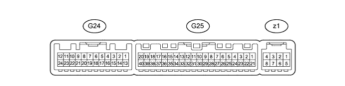
Terminal No. (Symbol) Wiring Color Terminal Description Condition Specified Condition G24-6 (SG-5) - Body ground R - Body ground Ground Always Below 1 Ω G24-8 (S5-2) - Body ground L - Body ground Power supply Ignition switch ON 4.5 to 5.5 V G24-9 (ROUT) - Body ground LG - Body ground Climate control blower control signal Ignition switch ON, refreshing seat switch on (blower position) Pulse generation (See waveform 1) G24-10 (LOUT) - Body ground V - Body ground Climate control blower control signal Ignition switch ON, refreshing seat switch on (blower position) Pulse generation (See waveform 1) G24-15 (SW5) - Body ground W - Body ground Output climate control signal (front passenger side) Ignition switch ON, refreshing seat switch blower side volume 3 Pulse generation (See waveform 2) G24-16 (SW4) - Body ground GR - Body ground Output climate control signal (driver side) Ignition switch ON, refreshing seat switch blower side volume 3 Pulse generation (See waveform 2) G25-31 (S5-4) - Body ground V - Body ground Power supply Ignition switch ON 4.5 to 5.5 V G25-35 (SG-4) - Body ground G - Body ground Ground Always Below 1 Ω
-
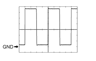
Using an oscilloscope, check waveform 1.
Measurement Condition Item Content Terminal No. (Symbol) G24-9 (ROUT) - Body ground
G24-10 (LOUT) - Body ground
Tool Setting 2 V/DIV., 500 μsec/DIV. Condition Ignition switch ON, refreshing seat switch on (blower position) -
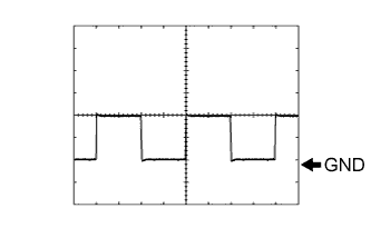
Using an oscilloscope, check waveform 2.
Measurement Condition Item Content Terminal No. (Symbol) G24-15 (SW5) - Body ground
G24-16 (SW4) - Body ground
Tool Setting 2 V/DIV., 500 μsec/DIV. Condition Ignition switch ON, refreshing seat switch blower side volume 3
-
-
-
AIR CONDITIONING CONTROL ASSEMBLY Click here