SEAT HEATER SYSTEM TERMINALS OF ECU

-
AIR CONDITIONING CONTROL ASSEMBLY
-
Measure the voltage and resistance according to the value(s) in the table below.
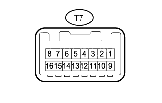
Terminal No. (Symbol) Wiring Color Terminal Description Condition Specified Condition T7-1 (IG) - Body ground L - Body ground Power supply Ignition switch ON 11 to 14 V T7-8 (E) - Body ground G - Body ground Ground Always Below 1 Ω
-