REAR POWER SEAT CONTROL SYSTEM Park / Neutral Position Switch Circuit
DESCRIPTION
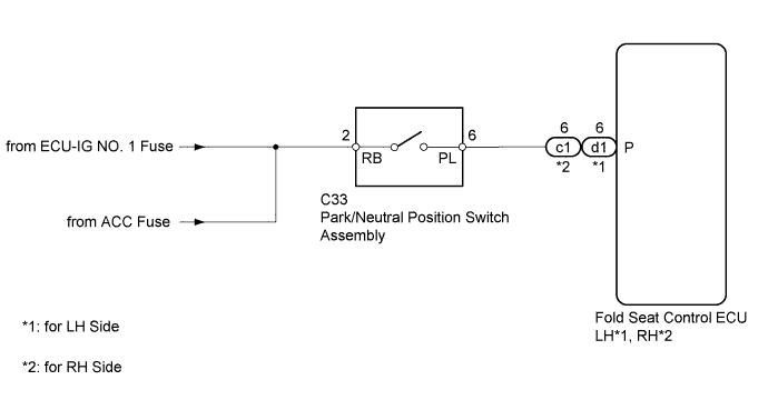
The fold seat control ECU receives signals from the park/neutral position switch and controls the seat folding and return operations. If the shift lever is in any position other than P when the ignition switch is ON, the seat cannot be operated.
WIRING DIAGRAM
INSPECTION PROCEDURE
PROCEDURE
-
CHECK FOLD SEAT CONTROL ECU (PARK/NEUTRAL POSITION SWITCH SIGNAL)
-
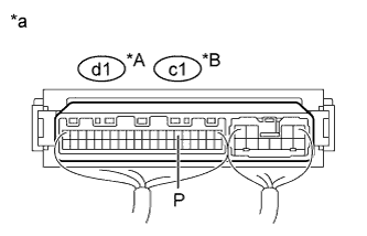
Text in Illustration *A for LH Side *B for RH Side *a Component with harness connected
(Fold Seat Control ECU)
Remove the fold seat control ECU with its connectors still connected Click here.
-
Measure the voltage according to the value(s) in the table below.
Standard Voltage for LH Side Tester Connection Condition Specified Condition d1-6 (P) - Body ground Ignition switch ACC or ON
Shift lever in P
11 to 14 V Ignition switch ACC or ON
Shift lever not in P
Below 1 V for RH Side Tester Connection Condition Specified Condition c1-6 (P) - Body ground Ignition switch ACC or ON
Shift lever in P
11 to 14 V Ignition switch ACC or ON
Shift lever not in P
Below 1 V
NG 
CHECK HARNESS AND CONNECTOR (PARK/NEUTRAL POSITION SWITCH - BATTERY) Click here
OK 
PROCEED TO NEXT SUSPECTED AREA SHOWN IN PROBLEM SYMPTOMS TABLE Click here
-
-
CHECK HARNESS AND CONNECTOR (PARK/NEUTRAL POSITION SWITCH - BATTERY)
-
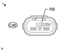
Text in Illustration *a Front view of wire harness connector
(to Park/Neutral Position Switch Assembly)
Disconnect the C40 switch connector.
-
Measure the voltage according to the value(s) in the table below.
Standard Voltage Tester Connection Switch Condition Specified Condition C40-2 (RB) - Body ground Ignition switch ACC or ON 11 to 14 V Ignition switch off Below 1 V
NG 
REPAIR OR REPLACE HARNESS OR CONNECTOR
OK 
-
-
INSPECT PARK/NEUTRAL POSITION SWITCH ASSEMBLY
-
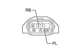
Disconnect the C40 switch connector.
-
Measure the resistance according to the value(s) in the table below.
Standard Resistance Tester Connection Condition Specified Condition 2 (RB) - 6 (PL) Shift lever in P Below 1 Ω 2 (RB) - 6 (PL) Shift lever not in P 10 kΩ or higher Result Result Proceed to OK A NG (for A343F Automatic Transmission) B NG (for A750F Automatic Transmission) C
B
REPLACE PARK/NEUTRAL POSITION SWITCH ASSEMBLY Click here
C
REPLACE PARK/NEUTRAL POSITION SWITCH ASSEMBLY Click here
A
-
-
CHECK HARNESS AND CONNECTOR (FOLD SEAT CONTROL ECU - PARK/NEUTRAL POSITION SWITCH)
-
Disconnect the d1*1 or c1*2 ECU connector.
-
*1: for LH Side
-
*2: for RH Side
-
-
Disconnect the C40 switch connector.
-
Measure the resistance according to the value(s) in the table below.
Standard Resistance for LH Side Tester Connection Condition Specified Condition d1-6 (P) - C40-6 (PL) Always Below 1 Ω d1-6 (P) - Body ground Always 10 kΩ or higher for RH Side Tester Connection Condition Specified Condition c1-6 (P) - C40-6 (PL) Always Below 1 Ω c1-6 (P) - Body ground Always 10 kΩ or higher
NG
REPAIR OR REPLACE HARNESS OR CONNECTOR
OK
REPLACE FOLD SEAT CONTROL ECU Click here
-