REAR POWER SEAT CONTROL SYSTEM TERMINALS OF ECU

-
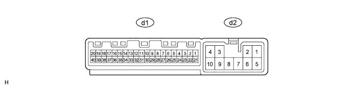
CHECK FOLD SEAT CONTROL ECU LH
-
Disconnect the d1 and d2 ECU connectors.
-
Measure the resistance and voltage according to the value(s) in the table below.
Terminal No.
(Symbol)
Wiring Color Terminal Description Condition Specified Condition d2-2 (+B) - d2-9 (GND2) R - W-B Power source (Battery) Always 11 to 14 V d2-9 (GND2) - Body ground W-B - Body ground Ground Always Below 1 Ω d2-10 (GND) - Body ground W-B - Body ground Ground Always Below 1 Ω d1-1 (ECUB) - d2-10 (GND) GR - W-B Power source (Battery) Always 11 to 14 V d1-3 (IG) - d2-9 (GND2) B - W-B Power source (IG) Ignition switch ON 11 to 14 V Ignition switch off Below 1 V d1-6 (P) - Body ground*1 W - Body ground Park/neutral position switch signal Ignition switch ON
Shift lever in P
11 to 14 V Ignition switch ON
Shift lever not in P
Below 1 V If the result is not as specified, there may be a malfunction on the wire harness side.
-
Reconnect the d1 and d2 ECU connectors.
-
Measure the resistance and voltage according to the value(s) in the table below.
Terminal No.
(Symbol)
Wiring Color Terminal Description Condition Specified Condition d2-1 (RCL+) - Body ground B - Body ground Reclining motor operation signal Rear power seat switch LH forward 11 to 14 V d2-5 (RCL-) - Body ground L - Body ground Reclining motor operation signal Rear power seat switch LH backward 11 to 14 V d2-8 (FLD+) - Body ground W - Body ground Cushion motor operation signal No. 1 or No. 2 fold seat switch LH fold 11 to 14 V d2-7 (FLD-) - Body ground B - Body ground Cushion motor operation signal No. 1 or No. 2 fold seat switch LH return 11 to 14 V d1-10 (FLD2) - Body ground GR - Body ground No. 1 fold seat switch signal (Fold) No. 1 fold seat switch LH off 11 to 14 V No. 1 fold seat switch LH fold Below 1 V d1-12 (RCLF) - Body ground P - Body ground Reclining forward switch signal Always 11 to 14 V Rear power seat switch LH forward Below 1 V d1-13 (RCLR) - Body ground Y - Body ground Reclining backward switch signal Always 11 to 14 V Rear power seat switch LH backward Below 1 V d1-14 (RTN2) - Body ground SB - Body ground No. 1 fold seat switch signal (Return) No. 1 fold seat switch LH off 11 to 14 V No. 1 fold seat switch LH return Below 1 V d1-15 (RTRN) - Body ground L - Body ground No. 2 fold seat switch signal (Return) No. 2 fold seat switch LH off 11 to 14 V No. 2 fold seat switch LH return Below 1 V d1-16 (FOLD) - Body ground V - Body ground No. 2 fold seat switch signal (Fold) No. 2 fold seat switch LH off 11 to 14 V No. 2 fold seat switch LH fold Below 1 V d1-17 (SV1) - d1-25 (SG1) P - R Folding position sensor power supply Ignition switch off Below 1 V Ignition switch ON 5.5 to 8 V d1-18 (SFLD) - d1-25 (SG1) G - R Folding position sensor signal Motor operating Pulse generation d1-19 (SRCL) - d1-24 (SG2) LG - W Reclining position sensor signal Motor operating Pulse generation d1-24 (SG2) - Body ground W - Body ground Reclining position sensor ground Always Below 1 Ω d1-25 (SG1) - Body ground R - Body ground Folding position sensor ground Always Below 1 Ω d1-37 (SV2) - d1-24 (SG2) GR - W Reclining position sensor power supply Ignition switch off Below 1 V Ignition switch ON 5.5 to 8 V d1-40 (PKB1) - Body ground*2 R - Body ground Parking brake switch signal Parking brake switch off 11 to 14 V Parking brake switch on Below 1 V
-
*1: for Automatic Transmission
-
*2: for Manual Transmission
If the result is not as specified, the ECU may have a malfunction.
-
-
-
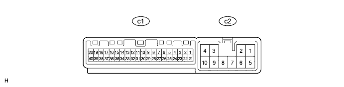
CHECK FOLD SEAT CONTROL ECU RH
-
Disconnect the c1 and c2 ECU connectors.
-
Measure the resistance and voltage according to the value(s) in the table below.
Terminal No.
(Symbol)
Wiring Color Terminal Description Condition Specified Condition c2-2 (+B) - c2-9 (GND2) R - W-B Power source (Battery) Always 11 to 14 V c2-9 (GND2) - Body ground W-B - Body ground Ground Always Below 1 Ω c2-10 (GND) - Body ground W-B - Body ground Ground Always Below 1 Ω c1-1 (ECUB) - c2-10 (GND) GR - W-B Power source (Battery) Always 11 to 14 V c1-3 (IG) - c2-9 (GND2) B - W-B Power source (IG) Ignition switch ON 11 to 14 V Ignition switch off Below 1 V c1-6 (P) - Body ground*1 W - Body ground Park/neutral position switch signal Ignition switch ON
Shift lever in P
11 to 14 V Ignition switch ON
Shift lever not in P
Below 1 V If the result is not as specified, there may be a malfunction on the wire harness side.
-
Reconnect the c1 and c2 ECU connectors.
-
Measure the resistance and voltage according to the value(s) in the table below.
Terminal No.
(Symbol)
Wiring Color Terminal Description Condition Specified Condition c2-1 (RCL+) - Body ground B - Body ground Reclining motor operation signal Rear power seat switch RH forward 11 to 14 V c2-5 (RCL-) - Body ground L - Body ground Reclining motor operation signal Rear power seat switch RH backward 11 to 14 V c2-8 (FLD+) - Body ground GR - Body ground Cushion motor operation signal No. 1 or No. 2 fold seat switch RH fold 11 to 14 V c2-7 (FLD-) - Body ground LG - Body ground Cushion motor operation signal No. 1 or No. 2 fold seat switch RH return 11 to 14 V c1-10 (FLD2) - Body ground GR - Body ground No. 1 fold seat switch signal (Fold) No. 1 fold seat switch RH off 11 to 14 V No. 1 fold seat switch RH fold Below 1 V c1-12 (RCLF) - Body ground P - Body ground Reclining forward switch signal Always 11 to 14 V Rear power seat switch RH forward Below 1 V c1-13 (RCLR) - Body ground Y - Body ground Reclining backward switch signal Always 11 to 14 V Rear power seat switch RH backward Below 1 V c1-14 (RTN2) - Body ground SB - Body ground No. 1 fold seat switch signal (Return) No. 1 fold seat switch RH off 11 to 14 V No. 1 fold seat switch RH return Below 1 V c1-15 (RTRN) - Body ground L - Body ground No. 2 fold seat switch signal (Return) No. 2 fold seat switch RH off 11 to 14 V No. 2 fold seat switch RH return Below 1 V c1-16 (FOLD) - Body ground V - Body ground No. 2 fold seat switch signal (Fold) No. 2 fold seat switch RH off 11 to 14 V No. 2 fold seat switch RH fold Below 1 V c1-17 (SV1) - c1-25 (SG1) P - R Folding position sensor power supply Ignition switch off Below 1 V Ignition switch ON 5.5 to 8 V c1-18 (SFLD) - c1-25 (SG1) G - R Folding position sensor signal Motor operating Pulse generation c1-19 (SRCL) - c1-24 (SG2) LG - W Reclining position sensor signal Motor operating Pulse generation c1-24 (SG2) - Body ground W - Body ground Reclining position sensor ground Always Below 1 Ω c1-25 (SG1) - Body ground R - Body ground Folding position sensor ground Always Below 1 Ω c1-37 (SV2) - c1-24 (SG2) GR - W Reclining position sensor power supply Ignition switch off Below 1 V Ignition switch ON 5.5 to 8 V c1-40 (PKB1) - Body ground*2 R - Body ground Parking brake switch signal Parking brake switch off 11 to 14 V Parking brake switch on Below 1 V
-
*1: for Automatic Transmission
-
*2: for Manual Transmission
If the result is not as specified, the ECU may have a malfunction.
-
-