REAR POWER SEAT CONTROL SYSTEM Rear Power Seat Switch Circuit
DESCRIPTION
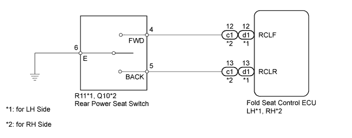
When the rear power seat switch is operated, a recline signal is sent to the fold seat control ECU. The ECU activates the power seat motor based on the signal from the rear power seat switch.
WIRING DIAGRAM
INSPECTION PROCEDURE
PROCEDURE
-
CHECK FOLD SEAT CONTROL ECU
-
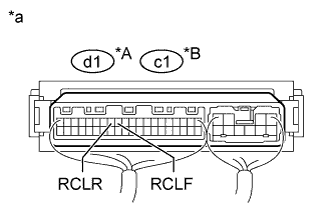
Text in Illustration *A for LH Side *B for RH Side *a Component with harness connected
(Fold Seat Control ECU)
Remove the fold seat control ECU with its connectors still connected Click here.
-
Measure the voltage according to the value(s) in the table below.
Standard Voltage for LH side Tester Connection Condition Specified Condition d1-12 (RCLF) - Body ground Always 11 to 14 V Rear power seat switch LH forward Below 1 V d1-13 (RCLR) - Body ground Always 11 to 14 V Rear power seat switch LH backward Below 1 V RH side Tester Connection Condition Specified Condition c1-12 (RCLF) - Body ground Always 11 to 14 V Rear power seat switch RH forward Below 1 V c1-13 (RCLR) - Body ground Always 11 to 14 V Rear power seat switch RH backward Below 1 V
NG 
INSPECT REAR POWER SEAT SWITCH Click here
OK 
PROCEED TO NEXT SUSPECTED AREA SHOWN IN PROBLEM SYMPTOMS TABLE Click here
-
-
INSPECT REAR POWER SEAT SWITCH
-
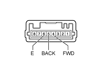
Remove the rear power seat switch Click here.
-
Measure the resistance according to the value(s) in the table below.
Standard Resistance Tester Connection Condition Specified Condition 4 (FWD) - 6 (E) Always 10 kΩ or higher Rear power seat switch forward Below 1 Ω 5 (BACK) - 6 (E) Always 10 kΩ or higher Rear power seat switch backward Below 1 Ω
NG 
REPLACE REAR POWER SEAT SWITCH Click here
OK 
-
-
CHECK HARNESS AND CONNECTOR (FOLD SEAT CONTROL ECU - REAR POWER SEAT SWITCH)
-
*1: for LH Side
-
*2: for RH Side
-
Disconnect the d1*1 or c1*2 ECU connector.
-
Disconnect the R11*1 or Q10*2 switch connector.
-
Measure the resistance according to the value(s) in the table below.
Standard Resistance for LH Side Tester Connection Condition Specified Condition d1-12 (RCLF) - R11-4 (FWD) Always Below 1 Ω d1-12 (RCLF) - Body ground Always 10 kΩ or higher d1-13 (RCLR) - R11-5 (BACK) Always Below 1 Ω d1-13 (RCLR) - Body ground Always 10 kΩ or higher for RH Side Tester Connection Condition Specified Condition c1-12 (RCLF) - Q10-4 (FWD) Always Below 1 Ω c1-12 (RCLF) - Body ground Always 10 kΩ or higher c1-13 (RCLR) - Q10-5 (BACK) Always Below 1 Ω c1-13 (RCLR) - Body ground Always 10 kΩ or higher
NG
REPAIR OR REPLACE HARNESS OR CONNECTOR
OK
REPLACE FOLD SEAT CONTROL ECU Click here
-