REAR POWER SEAT CONTROL SYSTEM Reclining Motor Circuit
DESCRIPTION
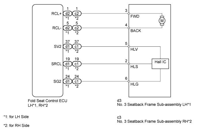
The fold seat control ECU receives switch operation signals from the No. 1 and No. 2 fold seat switches and rear power seat switch and activates the power seat motors. At this time, the Hall IC detects the actuation of the seatback and sends a seatback actuation signal to the fold seat control ECU. The fold seat control ECU uses signals from the Hall IC to detect if an object is caught or if any other abnormal condition has occurred.
WIRING DIAGRAM
INSPECTION PROCEDURE
PROCEDURE
-
INSPECT NO. 3 SEATBACK FRAME SUB-ASSEMBLY (RECLINING MOTOR)
-
for LH Side:
-
Remove the No. 3 seatback frame sub-assembly LH Click here.
-
Check if the No. 3 seatback frame moves smoothly when the battery is connected to the reclining motor connector terminals.
-
-
for RH Side:
-
Remove the No. 3 seatback frame sub-assembly RH Click here.
-
Check if the No. 3 seatback frame moves smoothly when the battery is connected to the reclining motor connector terminals.
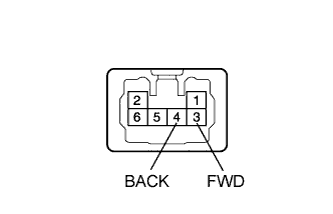
OK Measurement Condition Specified Condition Battery positive (+) → 3 (FWD)
Battery negative (-) → 4 (BACK)
Forward Battery positive (+) → 4 (BACK)
Battery negative (-) → 3 (FWD)
Backward Result Result Proceed to OK (for LH Side) A OK (for RH Side) B NG (for LH Side) C NG (for RH Side) D
-
B 
CHECK HARNESS AND CONNECTOR (FOLD SEAT CONTROL ECU - NO. 3 SEATBACK FRAME RH) Click here
C 
REPLACE NO. 3 SEATBACK FRAME SUB-ASSEMBLY LH Click here
D
REPLACE NO. 3 SEATBACK FRAME SUB-ASSEMBLY RH Click here
A 
-
-
CHECK HARNESS AND CONNECTOR (FOLD SEAT CONTROL ECU - NO. 3 SEATBACK FRAME LH)
-
Disconnect the d2 and d1 ECU connectors.
-
Disconnect the d3 No. 3 seatback frame connector.
-
Measure the resistance according to the value(s) in the table below.
Standard Resistance Tester Connection Condition Specified Condition d1-37 (SV2) - d3-5 (HLV) Always Below 1 Ω d1-37 (SV2) - Body ground Always 10 kΩ or higher d1-19 (SRCL) - d3-2 (HLS) Always Below 1 Ω d1-19 (SRCL) - Body ground Always 10 kΩ or higher d1-24 (SG2) - d3-6 (HLG) Always Below 1 Ω d1-24 (SG2) - Body ground Always 10 kΩ or higher d2-1 (RCL+) - d3-3 (FWD) Always Below 1 Ω d2-1 (RCL+) - Body ground Always 10 kΩ or higher d2-5 (RCL-) - d3-4 (BACK) Always Below 1 Ω d2-5 (RCL-) - Body ground Always 10 kΩ or higher
NG
REPAIR OR REPLACE HARNESS OR CONNECTOR
OK
-
-
CHECK FOLD SEAT CONTROL ECU LH
-
Remove the fold seat control ECU LH with its connectors still connected Click here.
-
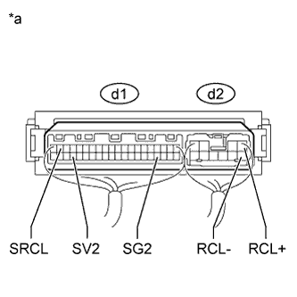
Text in Illustration *a Component with harness connected
(Fold Seat Control ECU LH)
Measure the voltage according to the value(s) in the table below.
Standard Voltage Tester Connection Condition Specified Condition d1-37 (SV2) - d1-24 (SG2) Ignition switch off Below 1 V Ignition switch ON 5.5 to 8 V d1-19 (SRCL) - d1-24 (SG2) Motor is operating Pulse generation d2-1 (RCL+) - Body ground Rear power seat switch LH forward 11 to 14 V d2-5 (RCL-) - Body ground Rear power seat switch LH backward 11 to 14 V
NG
REPLACE NO. 3 SEATBACK FRAME SUB-ASSEMBLY LH Click here
OK 
PROCEED TO NEXT SUSPECTED AREA SHOWN IN PROBLEM SYMPTOMS TABLE Click here
-
-
CHECK HARNESS AND CONNECTOR (FOLD SEAT CONTROL ECU - NO. 3 SEATBACK FRAME RH)
-
Disconnect the c2 and c1 ECU connectors.
-
Disconnect the c3 No. 3 seatback frame connector.
-
Measure the resistance according to the value(s) in the table below.
Standard Resistance Tester Connection Condition Specified Condition c1-37 (SV2) - c3-5 (HLV) Always Below 1 Ω c1-37 (SV2) - Body ground Always 10 kΩ or higher c1-19 (SRCL) - c3-2 (HLS) Always Below 1 Ω c1-19 (SRCL) - Body ground Always 10 kΩ or higher c1-24 (SG2) - c3-6 (HLG) Always Below 1 Ω c1-24 (SG2) - Body ground Always 10 kΩ or higher c2-1 (RCL+) - c3-3 (FWD) Always Below 1 Ω c2-1 (RCL+) - Body ground Always 10 kΩ or higher c2-5 (RCL-) - c3-4 (BACK) Always Below 1 Ω c2-5 (RCL-) - Body ground Always 10 kΩ or higher
NG
REPAIR OR REPLACE HARNESS OR CONNECTOR
OK
CHECK FOLD SEAT CONTROL ECU RH
-
-
CHECK FOLD SEAT CONTROL ECU RH
-
Remove the fold seat control ECU RH with its connectors still connected Click here.
-
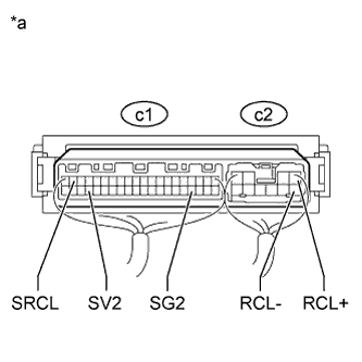
Text in Illustration *a Component with harness connected
(Fold Seat Control ECU RH)
Measure the voltage according to the value(s) in the table below.
Standard Voltage Tester Connection Condition Specified Condition c1-37 (SV2) - c1-24 (SG2) Ignition switch off Below 1 V Ignition switch ON 5.5 to 8 V c1-19 (SRCL) - c1-24 (SG2) Motor is operating Pulse generation c2-1 (RCL+) - Body ground Rear power seat switch RH forward 11 to 14 V c2-5 (RCL-) - Body ground Rear power seat switch RH backward 11 to 14 V
NG
REPLACE NO. 3 SEATBACK FRAME SUB-ASSEMBLY RH Click here
OK
PROCEED TO NEXT SUSPECTED AREA SHOWN IN PROBLEM SYMPTOMS TABLE Click here
-