SPIRAL CABLE INSPECTION

-
INSPECT SPIRAL CABLE SUB-ASSEMBLY (w/o Steering Heater)
-
If any of the defects mentioned below are found, replace the spiral cable sub-assembly with a new one:
Scratches, cracks, dents or chips on the connector or the spiral cable sub-assembly.
-
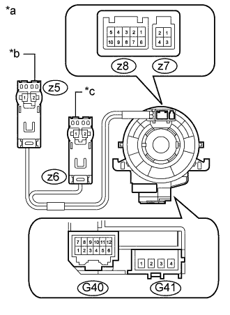
Text in Illustration *a Component without harness connected
(Spiral Cable Sub-assembly)
*b Orange *c Black Check the spiral cable sub-assembly.
-
Set the spiral cable sub-assembly to the center position Click here.
-
After setting the spiral cable sub-assembly to the center position, rotate the spiral cable sub-assembly 2.5 times clockwise and measure the resistance according to the value(s) in the table below. Then rotate the spiral cable sub-assembly 5 times counterclockwise and measure the resistance according to the value(s) in the table below.
Standard Resistance Tester Connection Condition Specified Condition G41-1 - z5-2 Always Below 1 Ω G41-2 - z5-1 Always Below 1 Ω G41-3 - z6-1 Always Below 1 Ω G41-4 - z6-2 Always Below 1 Ω G40-6 - z8-10 Always 3 Ω or less G40-5 - z8-9 Always 3 Ω or less G40-4 - z8-8 Always 3 Ω or less G40-3 - z8-7 Always 3 Ω or less G40-2 - z8-6 Always 3 Ω or less G40-2 - z7-4 Always 3 Ω or less G40-1 - z7-3 Always 3 Ω or less G40-12 - z8-5 Always 3 Ω or less G40-11 - z8-4 Always 3 Ω or less G40-10 - z8-3 Always 3 Ω or less G40-9 - z8-2 Always 3 Ω or less G40-8 - z8-1 Always 3 Ω or less G40-8 - z7-2 Always 3 Ω or less G40-7 - z7-1 Always 3 Ω or less -
After setting the spiral cable sub-assembly to the center position, rotate the spiral cable sub-assembly 2.5 times counterclockwise. Then while rotating the spiral cable sub-assembly 5 times clockwise, measure the resistance according to the value(s) in the table below.
Standard Resistance Tester Connection Condition Specified Condition G41-1 - z5-2 Always Below 1 Ω G41-2 - z5-1 Always Below 1 Ω G41-3 - z6-1 Always Below 1 Ω G41-4 - z6-2 Always Below 1 Ω G40-6 - z8-10 Always 3 Ω or less G40-5 - z8-9 Always 3 Ω or less G40-4 - z8-8 Always 3 Ω or less G40-3 - z8-7 Always 3 Ω or less G40-2 - z8-6 Always 3 Ω or less G40-2 - z7-4 Always 3 Ω or less G40-1 - z7-3 Always 3 Ω or less G40-12 - z8-5 Always 3 Ω or less G40-11 - z8-4 Always 3 Ω or less G40-10 - z8-3 Always 3 Ω or less G40-9 - z8-2 Always 3 Ω or less G40-8 - z8-1 Always 3 Ω or less G40-8 - z7-2 Always 3 Ω or less G40-7 - z7-1 Always 3 Ω or less Note
As the spiral cable sub-assembly may break, do not rotate the spiral cable sub-assembly more than the specified amount.
If the result is not as specified, replace the spiral cable sub-assembly.
-
-
-
INSPECT SPIRAL CABLE SUB-ASSEMBLY (w/ Steering Heater)
-
If any of the defects mentioned below are found, replace the spiral cable sub-assembly with a new one:
Scratches, cracks, dents or chips on the connector or the spiral cable sub-assembly.
-
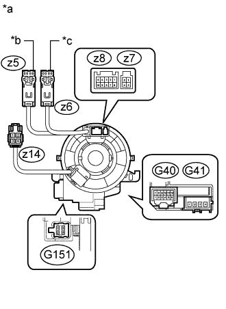
Text in Illustration *a Component without harness connected
(Spiral Cable Sub-assembly)
*b Orange *c Black Check the spiral cable sub-assembly.
-
Set the spiral cable sub-assembly to the center position Click here.
-
After setting the spiral cable sub-assembly to the center position, rotate the spiral cable sub-assembly 2.5 times clockwise and measure the resistance according to the value(s) in the table below. Then rotate the spiral cable sub-assembly 5 times counterclockwise and measure the resistance according to the value(s) in the table below.
Standard Resistance Tester Connection Condition Specified Condition G41-1 - z5-2 Always Below 1 Ω G41-2 - z5-1 Always Below 1 Ω G41-3 - z6-1 Always Below 1 Ω G41-4 - z6-2 Always Below 1 Ω G40-6 - z8-10 Always 3 Ω or less G40-5 - z8-9 Always 3 Ω or less G40-4 - z8-8 Always 3 Ω or less G40-3 - z8-7 Always 3 Ω or less G40-2 - z8-6 Always 3 Ω or less G40-2 - z7-4 Always 3 Ω or less G40-1 - z7-3 Always 3 Ω or less G40-12 - z8-5 Always 3 Ω or less G40-11 - z8-4 Always 3 Ω or less G40-10 - z8-3 Always 3 Ω or less G40-9 - z8-2 Always 3 Ω or less G40-8 - z8-1 Always 3 Ω or less G40-8 - z7-2 Always 3 Ω or less G40-7 - z7-1 Always 3 Ω or less z14-1 - G151-1 Always Below 0.1 Ω z14-2 - G151-3 Always Below 0.1 Ω z14-3 - G151-2 Always Below 0.1 Ω z14-4 - G151-4 Always Below 0.1 Ω -
After setting the spiral cable sub-assembly to the center position, rotate the spiral cable sub-assembly 2.5 times counterclockwise. Then while rotating the spiral cable sub-assembly 5 times clockwise, measure the resistance according to the value(s) in the table below.
Standard Resistance Tester Connection Condition Specified Condition G41-1 - z5-2 Always Below 1 Ω G41-2 - z5-1 Always Below 1 Ω G41-3 - z6-1 Always Below 1 Ω G41-4 - z6-2 Always Below 1 Ω G40-6 - z8-10 Always 3 Ω or less G40-5 - z8-9 Always 3 Ω or less G40-4 - z8-8 Always 3 Ω or less G40-3 - z8-7 Always 3 Ω or less G40-2 - z8-6 Always 3 Ω or less G40-2 - z7-4 Always 3 Ω or less G40-1 - z7-3 Always 3 Ω or less G40-12 - z8-5 Always 3 Ω or less G40-11 - z8-4 Always 3 Ω or less G40-10 - z8-3 Always 3 Ω or less G40-9 - z8-2 Always 3 Ω or less G40-8 - z8-1 Always 3 Ω or less G40-8 - z7-2 Always 3 Ω or less G40-7 - z7-1 Always 3 Ω or less z14-1 - G151-1 Always Below 0.1 Ω z14-2 - G151-3 Always Below 0.1 Ω z14-3 - G151-2 Always Below 0.1 Ω z14-4 - G151-4 Always Below 0.1 Ω Note
As the spiral cable sub-assembly may break, do not rotate the spiral cable sub-assembly more than the specified amount.
If the result is not as specified, replace the spiral cable sub-assembly.
-
-