METER / GAUGE SYSTEM, Diagnostic DTC:B2660

| DTC Code | DTC Name |
|---|---|
| B2660 | Steering Wheel Switch Malfunction |
DESCRIPTION
This code is output when any steering pad switch is continuously on for a period of 60 seconds.
| DTC Code | DTC Detection Condition | Trouble Area |
|---|---|---|
| B2660 | The driving support switch control ECU detects a malfunction in the steering pad switch. |
|
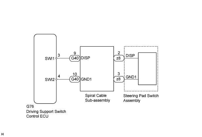
WIRING DIAGRAM
INSPECTION PROCEDURE
PROCEDURE
-
READ VALUE USING INTELLIGENT TESTER
-
Operate the intelligent tester according to the display and select the Data List Click here.
D-SEAT SW Tester Display Measurement Item/Range Normal Condition Diagnostic Note Steering Wheel Menu Switch MENU switch/OFF or ON OFF: MENU switch off - ON: MENU switch on Steering Wheel Enter Switch ENTER switch/OFF or ON OFF: ENTER switch off - ON: ENTER switch on Steering Wheel Up Switch UP/DOWN UP switch/OFF or ON OFF: UP/DOWN UP switch off - ON: UP/DOWN UP switch on Steering Wheel Down Switch UP/DOWN DOWN switch/OFF or ON OFF: UP/DOWN DOWN switch off - ON: UP/DOWN DOWN switch on OK The value displayed on the intelligent tester changes with the actual steering pad switch operation.
NG 
INSPECT STEERING PAD SWITCH ASSEMBLY Click here
OK 
REPLACE DRIVING SUPPORT SWITCH CONTROL ECU Click here
-
-
INSPECT STEERING PAD SWITCH ASSEMBLY
-
Remove the steering pad switch assembly Click here.
-
Measure the resistance according to the value(s) in the table below.
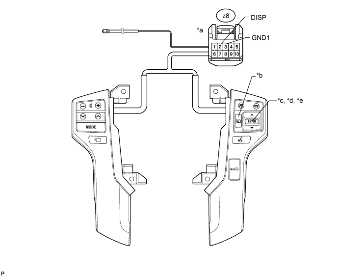
Standard Resistance Tester Connection Condition Specified Condition z8-2 (DISP) - z8-3 (GND1) MENU switch pushed Below 2.5 Ω ENTER switch pushed 313 to 346 Ω UP/DOWN UP switch pushed 3049 to 3370 Ω UP/DOWN DOWN switch pushed 959 to 1060 Ω switch off 95 to 105 kΩ Text in Illustration *a Front view of wire harness connector (to spiral cable sub-assembly) *b MENU switch *c ENTER switch *d UP/DOWN UP switch *e UP/DOWN DOWN switch
NG 
REPLACE STEERING PAD SWITCH ASSEMBLY Click here
OK 
-
-
INSPECT HARNESS AND CONNECTOR (SPIRAL CABLE - DRIVING SUPPORT SWITCH CONTROL ECU)
-
Disconnect the G76 driving support switch control ECU connector.
-
Disconnect the G40 spiral cable connector.
-
Measure the resistance according to the value(s) in the table below.
Standard Resistance Tester Connection Condition Specified Condition G40-9 (DISP) - G76-3 (SWI1) Always Below 1 Ω G40-10 (GND1) - G76-4 (SWI2) Always Below 1 Ω G40-9 (DISP) - G40-2 (ECC) Always 10 kΩ or higher G40-9 (DISP) - G40-4 (EAU) Always 10 kΩ or higher G40-9 (DISP) -G40-10 (GND1) Always 10 kΩ or higher G40-9 (DISP) - Body ground Always 10 kΩ or higher G40-10 (GND1) - Body ground Always 10 kΩ or higher
NG
REPAIR OR REPLACE HARNESS AND CONNECTOR
OK
-
-
INSPECT SPIRAL CABLE SUB-ASSEMBLY
-
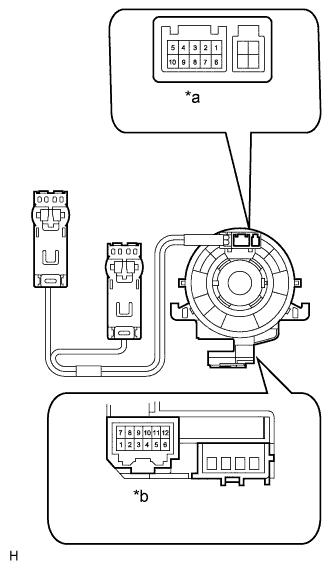
Text in Illustration *a Connector A *b Connector B Set the spiral cable to the center position Click here.
-
Measure the resistance according to the value(s) in the table below.
Standard Resistance Tester Connection Condition Specified Condition A-2 - B-9 Always Below 1 Ω A-3 - B-10 Always Below 1 Ω A-2 - A-3 Always 10 kΩ or higher A-2 - A-6 Always 10 kΩ or higher A-2 - A-8 Always 10 kΩ or higher A-2 - Body ground Always 10 kΩ or higher A-3 - Body ground Always 10 kΩ or higher
NG
REPLACE SPIRAL CABLE SUB-ASSEMBLY Click here
OK
REPLACE DRIVING SUPPORT SWITCH CONTROL ECU Click here
-