METER / GAUGE SYSTEM, Diagnostic DTC:B1500

| DTC Code | DTC Name |
|---|---|
| B1500 | Fuel Sender Open Detected |
DESCRIPTION
This DTC is stored when the combination meter detects a fuel sender gauge malfunction.
| DTC Code | DTC Detection Condition | Trouble Area |
|---|---|---|
| B1500 | When the combination meter detects a fuel sender gauge malfunction. |
|
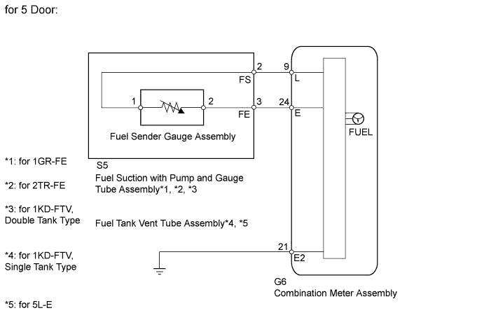
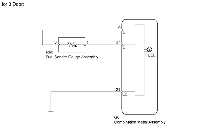
WIRING DIAGRAM
INSPECTION PROCEDURE
PROCEDURE
-
READ VALUE USING INTELLIGENT TESTER (FUEL SENDER GAUGE)
-
Operate the intelligent tester according to the display and select the Data List Click here.
Combination Meter Tester Display Measurement Item/Range Normal Condition Diagnostic Note Fuel Input Fuel sender gauge (main) input signal/Min.: 0, Max.: 127.5 Fuel sender input value Unit: L OK Fuel amount value displayed on the intelligent tester is almost the same as needle indication.
NG 
REPLACE COMBINATION METER ASSEMBLY Click here
OK 
-
-
CHECK HARNESS AND CONNECTOR (COMBINATION METER - FUEL SENDER GAUGE AND BODY GROUND)
-
Disconnect the G6 meter connector.
-
Disconnect the S5 gauge connector.
-
Disconnect the R40 gauge connector*.
-
Measure the resistance according to the value(s) in the table below.
Standard Resistance Tester Connection Condition Specified Condition G6-9 (L) - S5-2 (FS) Always Below 1 Ω G6-24 (E) - S5-3 (FE) G6-9 (L) - R40-3* G6-24 (E) - R40-1* G6-21 (E2) - Body ground
-
*: for 3 Door
-
NG
REPAIR OR REPLACE HARNESS OR CONNECTOR
OK
-
-
CHECK ENGINE TYPE
-
Check the engine type.
Engine Type Engine type Proceed to for 1GR-FE A for 2TR-FE B for 1KD-FTV C for 5L-E D
B 
INSPECT FUEL SUCTION WITH PUMP AND GAUGE TUBE ASSEMBLY (for 2TR-FE) Click here
C
CHECK FUEL TANK TYPE Click here
D
INSPECT FUEL TANK VENT TUBE ASSEMBLY (for 5L-E) Click here
A
-
-
INSPECT FUEL SUCTION WITH PUMP AND GAUGE TUBE ASSEMBLY (for 1GR-FE)
-
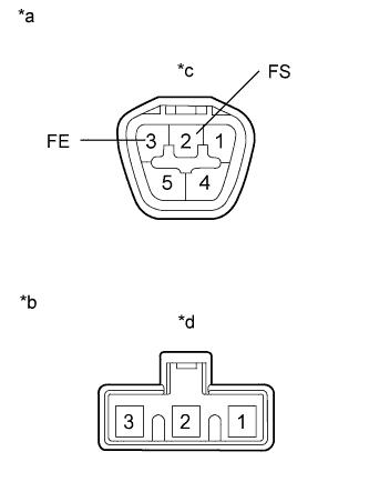
Text in Illustration *a Component without harness connected (Fuel Suction With Pump and Gauge Tube Assembly) *b Lower side (to Fuel Sender Gauge Assembly) *c Connector A *d Connector B Remove the fuel sender gauge.
-
for 1GR-FE, Single Tank Type: Click here
-
for 1GR-FE, Double Tank Type: Click here
-
-
Measure the resistance according to the value(s) in the table below.
Standard Resistance Tester Connection Condition Specified Condition A-2 (FS) - B-2 Always Below 1 Ω A-3 (FE) - B-1 Result Result Proceed to OK A NG (for Single Tank Type) B NG (for Double Tank Type) C
B
REPLACE FUEL SUCTION WITH PUMP AND GAUGE TUBE ASSEMBLY Click here
C
REPLACE FUEL SUCTION WITH PUMP AND GAUGE TUBE ASSEMBLY Click here
A
-
-
INSPECT FUEL SENDER GAUGE ASSEMBLY (for 1GR-FE)
-
Text in Illustration *a Front view of wire harness connector (to Fuel Sender Gauge Assembly) *b Float Level F (Upper) *c Float Level E (Lower) Measure the resistance according to the value(s) in the table below.
Standard Resistance Tester Connection Condition Specified Condition 1 - 2 Float level is F 12 to 18 Ω Float level is E 405 to 415 Ω Result Result Proceed to OK A NG (for Single Tank Type) B NG (for Double Tank Type) C
B
REPLACE FUEL SENDER GAUGE ASSEMBLY Click here
C
REPLACE FUEL SENDER GAUGE ASSEMBLY Click here
A 
REPLACE COMBINATION METER ASSEMBLY Click here
-
-
INSPECT FUEL SUCTION WITH PUMP AND GAUGE TUBE ASSEMBLY (for 2TR-FE)
Note
For 3 door vehicles, proceed to next step.
-
Text in Illustration *a Component without harness connected (Fuel Suction With Pump and Gauge Tube Assembly) *b Lower side (to Fuel Sender Gauge Assembly) *c Connector A *d Connector B Remove the fuel sender gauge.
-
for 2TR-FE, Single Tank Type: Click here
-
for 2TR-FE, Double Tank Type: Click here
-
-
Measure the resistance according to the value(s) in the table below.
Standard Resistance Tester Connection Condition Specified Condition A-2 (FS) - B-2 Always Below 1 Ω A-3 (FE) - B-1 Result Result Proceed to OK A NG (for Single Tank Type) B NG (for Double Tank Type) C
B
REPLACE FUEL SUCTION WITH PUMP AND GAUGE TUBE ASSEMBLY Click here
C
REPLACE FUEL SUCTION WITH PUMP AND GAUGE TUBE ASSEMBLY Click here
A
-
-
INSPECT FUEL SENDER GAUGE ASSEMBLY (for 2TR-FE)
for 3 Door:
-
Remove the fuel sender gauge Click here.
-
Text in Illustration *a Component without harness connected (Fuel Sender Gauge Assembly) *b Float Level F (Upper) *c Float Level E (Lower) Measure the resistance according to the value(s) in the table below.
Standard Resistance Tester Connection Condition Specified Condition 1 - 3 Float level is F 12 to 18 Ω Float level is E 405 to 415 Ω for 5 Door:
-
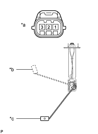
Text in Illustration *a Front view of wire harness connector (Fuel Sender Gauge Assembly) *b Float Level F (Upper) *c Float Level E (Lower) Measure the resistance according to the value(s) in the table below.
Standard Resistance Tester Connection Condition Specified Condition 1 - 2 Float level is F 12 to 18 Ω Float level is E 405 to 415 Ω Result Result Proceed to OK A NG (for Single Tank Type) B NG (for Double Tank Type) C
B
REPLACE FUEL SENDER GAUGE ASSEMBLY Click here
C
REPLACE FUEL SENDER GAUGE ASSEMBLY Click here
A
REPLACE COMBINATION METER ASSEMBLY Click here
-
-
CHECK FUEL TANK TYPE
-
Check the fuel tank type.
Fuel Tank Type Fuel Tank Type Proceed to Single tank type A Double tank type B
B
INSPECT FUEL SUCTION WITH PUMP AND GAUGE TUBE ASSEMBLY (for 1KD-FTV, DOUBLE TANK TYPE) Click here
A
-
-
INSPECT FUEL TANK VENT TUBE ASSEMBLY (for 1KD-FTV, SINGLE TANK TYPE)
Note
For 3 door vehicles, proceed to next step.
-
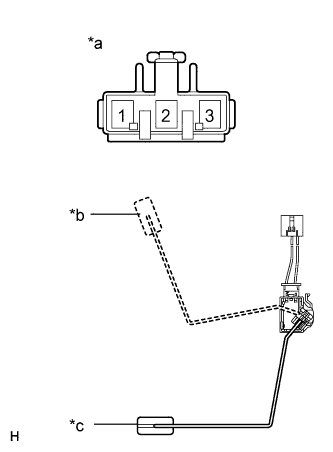
Text in Illustration *a Component without harness connected (Fuel Tank Vent Tube Assembly) *b Lower side (to Fuel Sender Gauge Assembly) *c Connector A *d Connector B Remove the fuel sender gauge.
-
for 1KD-FTV, Single Tank Type: Click here
-
-
Measure the resistance according to the value(s) in the table below.
Standard Resistance Tester Connection Condition Specified Condition A-2 (FS) - B-2 Always Below 1 Ω A-3 (FE) - B-1
NG
REPLACE FUEL TANK VENT TUBE ASSEMBLY Click here
OK
-
-
INSPECT FUEL SENDER GAUGE ASSEMBLY (for 1KD-FTV, SINGLE TANK TYPE)
for 3 Door:
-
Remove the fuel sender gauge.
-
for 1KD-FTV, Single Tank Type: Click here
-
-
Text in Illustration *a Component without harness connected (Fuel Sender Gauge Assembly) *b Float Level F (Upper) *c Float Level E (Lower) Measure the resistance according to the value(s) in the table below.
Standard Resistance Tester Connection Condition Specified Condition 1 - 3 Float level is F 12 to 18 Ω Float level is E 405 to 415 Ω for 5 Door:
-
Text in Illustration *a Front view of wire harness connector (Fuel Sender Gauge Assembly) *b Float Level F (Upper) *c Float Level E (Lower) Measure the resistance according to the value(s) in the table below.
Standard Resistance Tester Connection Condition Specified Condition 1 - 2 Float level is F 12 to 18 Ω Float level is E 405 to 415 Ω
NG
REPLACE FUEL SENDER GAUGE ASSEMBLY Click here
OK
REPLACE COMBINATION METER ASSEMBLY Click here
-
-
INSPECT FUEL SUCTION WITH PUMP AND GAUGE TUBE ASSEMBLY (for 1KD-FTV, DOUBLE TANK TYPE)
-
Text in Illustration *a Component without harness connected (Fuel Suction With Pump and Gauge Tube Assembly) *b Lower side (to Fuel Sender Gauge Assembly) *c Connector A *d Connector B Remove the fuel sender gauge.
-
for 1KD-FTV, Double Tank Type: Click here
-
-
Measure the resistance according to the value(s) in the table below.
Standard Resistance Tester Connection Condition Specified Condition A-2 (FS) - B-2 Always Below 1 Ω A-3 (FE) - B-1 Result Result Proceed to OK A NG (for Single Tank Type) B NG (for Double Tank Type) C
NG
REPLACE FUEL SUCTION WITH PUMP AND GAUGE TUBE ASSEMBLY Click here
OK
-
-
INSPECT FUEL SENDER GAUGE ASSEMBLY (for 1KD-FTV, DOUBLE TANK TYPE)
-
Text in Illustration *a Front view of wire harness connector (Fuel Sender Gauge Assembly) *b Float Level F (Upper) *c Float Level E (Lower) Measure the resistance according to the value(s) in the table below.
Standard Resistance Tester Connection Condition Specified Condition 1 - 2 Float level is F 12 to 18 Ω Float level is E 405 to 415 Ω Result Result Proceed to OK A NG (for Single Tank Type) B NG (for Double Tank Type) C
NG
REPLACE FUEL SENDER GAUGE ASSEMBLY Click here
OK
REPLACE COMBINATION METER ASSEMBLY Click here
-
-
INSPECT FUEL TANK VENT TUBE ASSEMBLY (for 5L-E)
-
Text in Illustration *a Component without harness connected (Fuel Tank Vent Tube Assembly) *b Lower side (Fuel Sender Gauge Assembly) *c Connector A *d Connector B Remove the fuel sender gauge.
-
for 5L-E, Single Tank Type: Click here
-
for 5L-E, Double Tank Type: Click here
-
-
Measure the resistance according to the value(s) in the table below.
Standard Resistance Tester Connection Condition Specified Condition A-2 (FS) - B-2 Always Below 1 Ω A-3 (FE) - B-1 Result Result Proceed to OK A NG (for Single Tank Type) B NG (for Double Tank Type) C
B
REPLACE FUEL TANK VENT TUBE ASSEMBLY Click here
C
REPLACE FUEL TANK VENT TUBE ASSEMBLY Click here
A
-
-
INSPECT FUEL SENDER GAUGE ASSEMBLY (for 5L-E)
-
Text in Illustration *a Front view of wire harness connector (Fuel Sender Gauge Assembly) *b Float Level F (Upper) *c Float Level E (Lower) Measure the resistance according to the value(s) in the table below.
Standard Resistance Tester Connection Condition Specified Condition 1 - 2 Float level is F 12 to 18 Ω Float level is E 405 to 415 Ω Result Result Proceed to OK A NG (for Single Tank Type) B NG (for Double Tank Type) C
B
REPLACE FUEL SENDER GAUGE ASSEMBLY Click here
C
REPLACE FUEL SENDER GAUGE ASSEMBLY Click here
A
REPLACE COMBINATION METER ASSEMBLY Click here
-