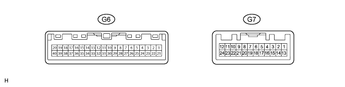
METER / GAUGE SYSTEM TERMINALS OF ECU

-
COMBINATION METER ASSEMBLY
-
Measure the voltage and resistance according to the value(s) in the table below.
Terminal No. (Symbol) Wiring Color Terminal Description Condition Specified Condition G6-5 (ET) - Body ground*1 G - Body ground Ground Always Below 1 Ω G6-6 (SW1) - Body ground B - Body ground Power source for light control rheostat Ignition switch ON 4.6 to 5.4 V G6-7 (SW2) - Body ground GR - Body ground Light control rheostat signal Light control rheostat fully turned right Below 1 Ω Light control rheostat fully turned left 8 to 12 kΩ G6-8 (L) - Body ground*1 W - Body ground Fuel sender gauge signal Fuel F (full tank) → E (empty) Below 1 V → 4.5 to 9 V G6-9 (L) - Body ground B - Body ground Fuel sender gauge signal Fuel F (full tank) → E (empty) Below 1 V → 4.5 to 9 V G6-10 (TC) - Body ground*2 W - Body ground TAIL cancel switch signal TAIL cancel switch on Below 1 Ω TAIL cancel switch off 1 MΩ or higher G6-11 (RSET) - Body ground P - Body ground ODO/TRIP switch signal Ignition switch ON, ODO/TRIP switch on (Pushed) Below 1 Ω Ignition switch ON, ODO/TRIP switch off (Not pushed) 1 MΩ or higher G6-13 (BLP) - Body ground*3 R - Body ground Back-up light switch signal Ignition switch ON, Back-up light switch on 11 to 14 V G6-14 (ST) - Body ground*3 W - Body ground Starter signal Clutch start switch on, Cranking 5.5 V or higher G6-15 (TCO) - Body ground*4 V - Body ground DLC3 (TC) Ignition switch ON 11 to 14 V G6-19 (B) - Body ground Y - Body ground Turn signal LH Ignition switch ON, turn LH indicator light blinks Below 1 V ←→ 11 to 14 V Ignition switch ON, turn signal switch neutral position Below 1 V G6-20 (B) - Body ground G - Body ground Turn signal RH Ignition switch ON, turn RH indicator light blinks Below 1 V ←→ 11 to 14 V Ignition switch ON, turn signal switch neutral position Below 1 V G6-21 (E2) - Body ground BR - Body ground Signal ground Always Below 1 V G6-22 (SW3) - Body ground LG - Body ground Light control rheostat ground Always Below 1 V G6-23 (FE) - Body ground*1 B - Body ground Fuel sender gauge ground Always Below 1 Ω G6-24 (E) - Body ground W - Body ground Fuel sender gauge ground Always Below 1 Ω G6-26 (B) - Body ground L - Body ground Battery Always 11 to 14 V G6-28 (IG+) - Body ground R - Body ground Ignition switch signal Ignition switch ON 11 to 14 V Ignition switch off Below 1 V G6-30 (CHG-) - Body ground P - Body ground Charge warning light signal Ignition switch ON, charge warning light on Below 1 V Ignition switch ON, charge warning light off 11 to 14 V G6-31 (SW) - Body ground P - Body ground Fluid level warning switch signal Ignition switch ON, fluid level warning switch on Below 1 V Ignition switch ON, fluid level warning switch off 11 to 14 V G6-32 (+S) - Body ground R - Body ground Speed signal for other systems (Output) Ignition switch ON, front wheel turns slowly Pulse generation
(See waveform 1)
G6-33 (SI) - Body ground V - Body ground Speed signal for other systems (Input) Ignition switch ON, front wheel turns slowly Pulse generation
(See waveform 1)
G6-34 (S) - Body ground*4 P - Body ground Engine speed signal Idling with warm engine Pulse generation
(See waveform 2)
G6-35 (TEMP) - Body ground*4 L - Body ground Engine coolant temperature signal Idling with warm engine Pulse generation
(See waveform 3)
G6-37 (LIN) - Body ground GR - Body ground LIN communication signal Ignition switch ON Pulse generation G6-39 (CANL) - Body ground W - Body ground CAN communication signal Ignition switch off 200 Ω or higher G6-40 (CANH) - Body ground LG - Body ground*6, *7, *8 CAN communication signal Ignition switch off 200 Ω or higher V - Body ground*9, *10 G7-1 (ED) - Body ground*11 W-B - Body ground Vehicle type for 3 door Below 1 V for 5 door 4.6 to 5.4 V G7-3 (S) - Body ground*4, *12 R - Body ground Fuel sedimenter warning switch signal Ignition switch ON, fuel sedimenter warning switch on Below 1 V Ignition switch ON, fuel sedimenter warning switch off 11 to 14 V G7-4 (FFTR) - Body ground*12 V - Body ground Fuel filter warning switch signal Ignition switch ON, fuel filter warning switch on Below 1 V Ignition switch ON, fuel filter warning switch off 11 to 14 V G7-5 (OIL) - Body ground*12, *13 G - Body ground Oil level sensor signal Ignition switch ON, oil level warning light comes on Below 1 V Ignition switch ON, oil level warning light off 11 to 14 V G7-7 (CHK) - Body ground V - Body ground MIL (Malfunction Indicator Lamp) signal Ignition switch ON, MIL (Malfunction Indicator Lamp) comes on Below 1 V Ignition switch ON, MIL (Malfunction Indicator Lamp) off 11 to 14 V G7-8 (GLW-) - Body ground*4 R - Body ground GLOW indicator light signal Ignition switch ON, GLOW indicator light comes on Below 1 V Ignition switch ON, GLOW indicator light off 11 to 14 V G7-15 (P/SB) - Body ground L - Body ground Passenger side seat belt buckle switch Ignition switch ON, sit on the front passenger seat, and front passenger side seat belt unfastened 11 to 14 V Ignition switch ON, sit on the front passenger seat, and front passenger side seat belt fastened Below 1 V G7-16 (TIRE) - Body ground*14 Y - Body ground Tire pressure warning light signal Ignition switch ON, tire pressure warning light off 3.2 V or higher Ignition switch ON, tire pressure warning light on 0.9 to 3.2 V G7-17 (EC) - Body ground*14 BR - Body ground Tire pressure warning light ground Always Below 1 Ω G7-20 (WLVL) - Body ground*5 W - Body ground Washer level warning signal Ignition switch ON, level warning switch on Below 1 V Ignition switch ON, level warning switch off 11 to 14 V G7-23 (VCM) - Body ground*4 G - Body ground Vacuum warning switch signal Ignition switch ON, vacuum warning switch on Below 1 V Ignition switch ON, vacuum warning switch off 11 to 14 V G7-24 (S) - Body ground V - Body ground Oil pressure switch signal Ignition switch ON, oil pressure warning light on Below 1 V Ignition switch ON, oil pressure warning light off 11 to 14 V
-
*1: for Double Tank Type
-
*2: w/ TAIL Cancel Switch
-
*3: for Manual Transmission
-
*4: for 5L-E
-
*5: for Cold Area
-
*6: for RHD
-
*7: for LHD, 1GR-FE
-
*8: for LHD, 1KD-FTV
-
*9: for LHD, 2TR-FE
-
*10: for LHD, 5L-E
-
*11: except 5L-E
-
*12: for 1KD-FTV
-
*13: for Europe, 1GR-FE
-
*14: w/ Tire Pressure Monitor System
-
-
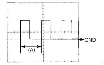
Waveform 1 (Reference): Using an oscilloscope:
Item Condition Tool setting 5 V/DIV., 20 ms./DIV. Vehicle condition Driving at approximately 20 km/h (12 mph) Tech Tips
When the system is functioning normally, one wheel revolution generates 4 pulses. As the vehicle speed increases, the width indicated by (A) in the illustration narrows.
-
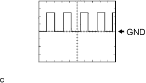
Waveform 2 (Reference): Using an oscilloscope:
Item Condition Tool setting 5 V/DIV., 20 ms./DIV. Vehicle condition Idling with warm engine -
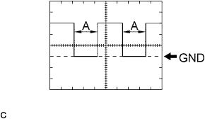
Waveform 3 (Reference): Using an oscilloscope:
Item Condition Tool setting 5 V/DIV., 0.1 sec./DIV. Vehicle condition Idling
-
-
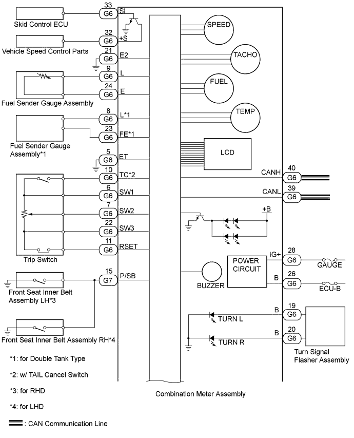
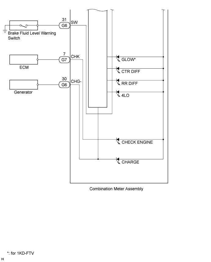
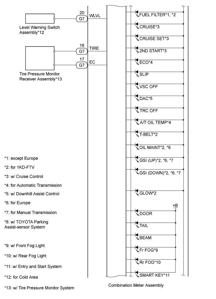
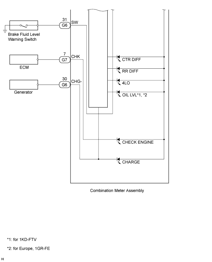
COMBINATION METER ASSEMBLY INNER CIRCUIT (for Optitron Meter)

-
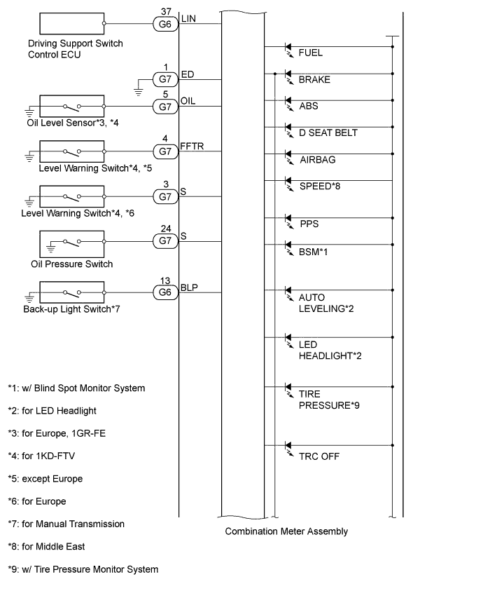
COMBINATION METER ASSEMBLY INNER CIRCUIT (for Analog Meter, except 5L-E)
-
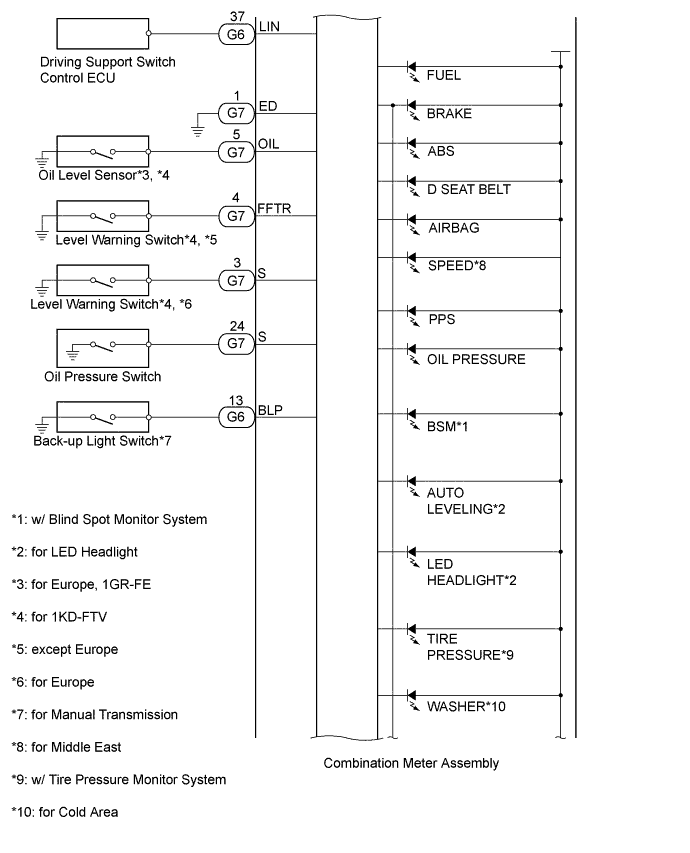
COMBINATION METER ASSEMBLY INNER CIRCUIT (for Analog Meter, for 5L-E)
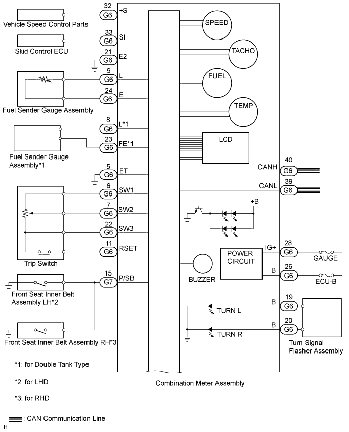
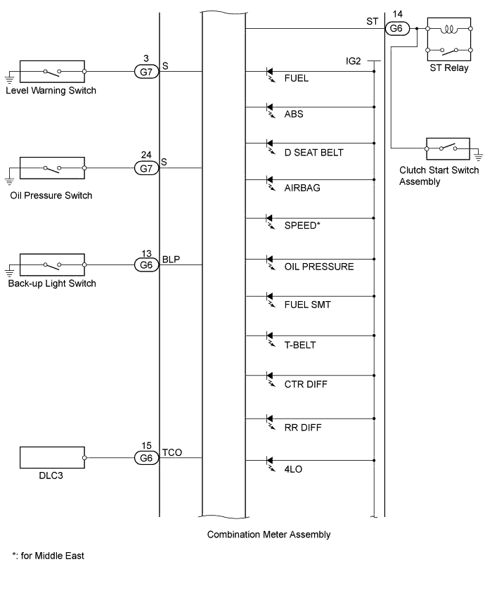
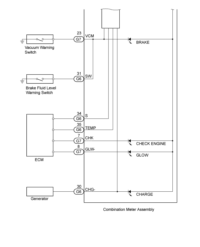
Terminal No. (Symbol) Wire Harness Side G6 1 - 2 - 3 - 4 - 5 (ET) Ground 6 (SW1) TRIP switch (Light control rheostat) 7 (SW2) TRIP switch (Light control rheostat) 8 (L)*1 Fuel sender gauge assembly 9 (L) Fuel sender gauge assembly 10 (TC)*2 TRIP switch (TAIL cancel switch) 11 (RSET) ODO/TRIP switch 12 - 13 (BLP)*3 Back-up light switch 14 (ST)*4 ST relay, clutch start switch 15 (TCO)*4 DLC3 16 - 17 - 18 - 19 (B) Turn signal flasher assembly 20 (B) Turn signal flasher assembly 21 (E2) Ground 22 (SW3) TRIP switch (Light control rheostat) 23 (FE)*1 Fuel sender gauge assembly 24 (E) Fuel sender gauge assembly 25 - 26 (B) Battery 27 - 28 (IG+) Ignition switch 29 - 30 (CHG-) Generator 31 (SW) Fluid level warning switch 32 (+S) Each part that uses the vehicle speed signal 33 (SI) Skid control ECU 34 (S)*4 ECM 35 (TEMP)*4 ECM 36 - 37 (LIN)*5 Accessory meter 38 - 39 (CANL) CAN communication line 40 (CANH) CAN communication line G7 1 (ED)*6 Ground 2 - 3 (S)*4, *7 Fuel sedimenter warning switch 4 (FFTR)*7 Fuel filter warning switch 5 (OIL)*7, *8 Oil Level Sensor 6 - 7 (CHK) ECM 8 (GLW-)*4 ECM 9 - 10 - 11 - 12 - 13 - 14 - 15 (P/SB) Passenger side seat belt buckle switch 16 (TIRE)*9 Tire pressure monitor receiver assembly 17 (EC)*9 Tire pressure monitor receiver assembly 18 - 19 - 20 (WLVL)*10 Level warning switch assembly 21 - 22 - 23 (VCM)*4 Vacuum warning switch 24 (S) Oil pressure switch
-
*1: for Double Tank Type
-
*2: w/ TAIL Cancel Switch
-
*3: for Manual Transmission
-
*4: for 5L-E
-
*5: w/ Multi-function Switch
-
*6: except 5L-E
-
*7: for 1KD-FTV
-
*8: for Europe, 1GR-FE
-
*9: w/ Tire Pressure Monitor System
-
*10: for Cold Area
-