LIGHTING SYSTEM Interior Light Switch Signal Circuit
DESCRIPTION
The main body ECU detects the condition of the interior light switch.
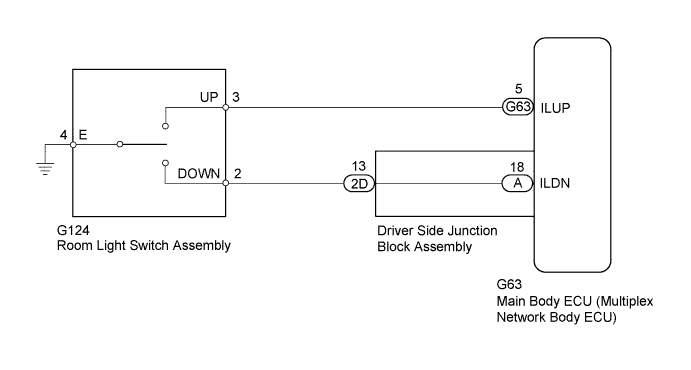
WIRING DIAGRAM
INSPECTION PROCEDURE
PROCEDURE
-
READ VALUE USING INTELLIGENT TESTER (ROOM LIGHT SWITCH)
-
Using the intelligent tester, read the Data List Click here.
Main Body Tester Display Measurement Item/Range Normal Condition Diagnostic Note Lounge Illumination Value SW (UP) Room light switch (up) signal / ON or OFF ON: Room light switch (up) on
OFF: Room light switch (up) off
- Lounge Illumination Value SW (Dwn) Room light switch (down) signal / ON or OFF ON: Room light switch (down) on
OFF: Room light switch (down) off
- OK Switch condition is displayed.
NG 
INSPECT ROOM LIGHT SWITCH ASSEMBLY Click here
OK 
PROCEED TO NEXT SUSPECTED AREA SHOWN IN PROBLEM SYMPTOMS TABLE Click here
-
-
INSPECT ROOM LIGHT SWITCH ASSEMBLY
-
Remove the room light switch Click here.
-
Measure the resistance according to the value(s) in the table.
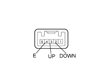
Standard Resistance Tester Connection Switch Condition Specified Condition 3 (UP) - 4 (E) Room light switch up Below 1 Ω Room light switch off 10 kΩ or higher 2 (DOWN) - 4 (E) Room light switch down Below 1 Ω Room light switch off 10 kΩ or higher
NG 
REPLACE ROOM LIGHT SWITCH ASSEMBLY Click here
OK 
-
-
CHECK HARNESS AND CONNECTOR (ROOM LIGHT SWITCH ASSEMBLY - MAIN BODY ECU, DRIVER SIDE JUNCTION BLOCK AND BODY GROUND)
-
Disconnect the G124 room light switch connector.
-
Disconnect the 2D driver side junction block connector.
-
Disconnect the G63 main body ECU connector.
-
Measure the resistance according to the value(s) in the table.
Standard Resistance Tester Connection Condition Specified Condition G124-3 (UP) - G63-5 (ILUP) Always Below 1 Ω G124-2 (DOWN) - 2D-13 Always Below 1 Ω G124-4 (E) - Body ground Always Below 1 Ω G124-3 (UP) or G63-5 (ILUP) - Body ground Always 10 kΩ or higher G124-2 (DOWN) or 2D-13 - Body ground Always 10 kΩ or higher
NG
REPAIR OR REPLACE HARNESS OR CONNECTOR
OK
-
-
CHECK DRIVER SIDE JUNCTION BLOCK ASSEMBLY
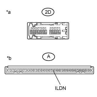
Text in Illustration *a Front view of wire harness connector
(to Driver Side Junction Block Assembly)
*b Front view of wire harness connector
(to Main Body ECU)
-
Disconnect the 2D driver side junction block connector.
-
Remove the main body ECU Click here.
-
Measure the resistance according to the value(s) in the table.
Standard Resistance Tester Connection Condition Specified Condition 2D-13 - A-18 (ILDN) Always Below 1 Ω 2D-13 - Body ground Always 10 kΩ or higher
NG
REPLACE DRIVER SIDE JUNCTION BLOCK ASSEMBLY Click here
OK
REPLACE MAIN BODY ECU (MULTIPLEX NETWORK BODY ECU) Click here
-