LIGHTING SYSTEM Back Door Courtesy Switch Circuit
DESCRIPTION
The main body ECU receives a door open/closed signal from each door courtesy light switch.
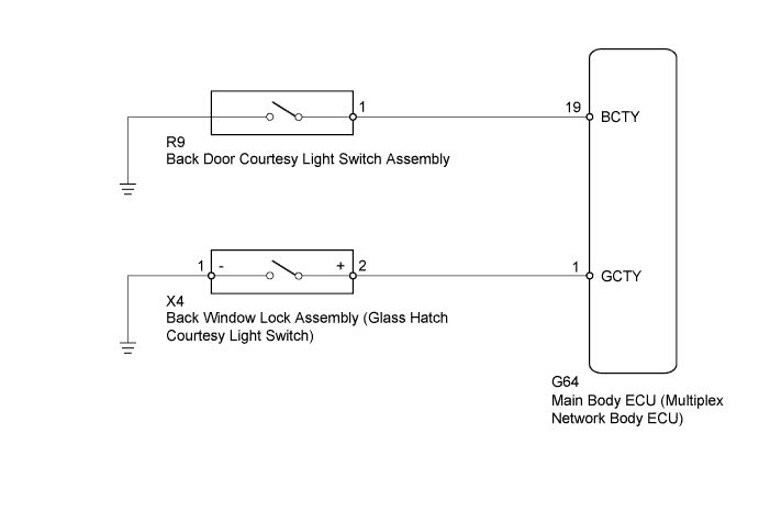
WIRING DIAGRAM
INSPECTION PROCEDURE
PROCEDURE
-
READ VALUE USING INTELLIGENT TESTER (DOOR COURTESY LIGHT SWITCH)
-
Using the intelligent tester, read the Data List Click here.
Main Body Tester Display Measurement Item/Range Normal Condition Diagnostic Note Back Door Courtesy SW Back door courtesy switch signal / ON or OFF ON: Back door open
OFF: Back door closed
- Glass Hatch Courtesy Switch* Glass hatch courtesy switch signal / ON or OFF ON: Glass hatch open
OFF: Glass hatch closed
-
-
*: w/ Glass Hatch Opener System
OK The display is as specified in the normal condition column. Result Result Proceed to OK A NG (Back door courtesy light switch does not operate) B NG (Glass hatch courtesy light switch does not operate) C -
B 
INSPECT BACK DOOR COURTESY LIGHT SWITCH ASSEMBLY Click here
C
INSPECT BACK WINDOW LOCK ASSEMBLY (GLASS HATCH COURTESY LIGHT SWITCH) Click here
A 
PROCEED TO NEXT SUSPECTED AREA SHOWN IN PROBLEM SYMPTOMS TABLE Click here
-
-
INSPECT BACK DOOR COURTESY LIGHT SWITCH ASSEMBLY
-
Remove the back door courtesy light switch Click here.
-
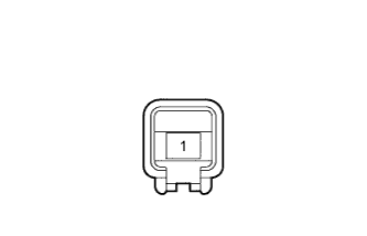
Measure the resistance according to the value(s) in the table below.
Standard Resistance Tester Connection Switch Condition Specified Condition 1 - Switch body Pin not pushed Below 1 Ω Pin pushed 10 kΩ or higher
NG 
REPLACE BACK DOOR COURTESY LIGHT SWITCH ASSEMBLY Click here
OK 
-
-
CHECK HARNESS AND CONNECTOR (MAIN BODY ECU - BACK DOOR COURTESY LIGHT SWITCH ASSEMBLY)
-
Disconnect the G64 main body ECU connector.
-
Disconnect the R9 back door courtesy light switch connector.
-
Measure the resistance according to the value(s) in the table below.
Standard Resistance Tester Connection Condition Specified Condition G64-19 (BCTY) - R9-1 Always Below 1 Ω G64-19 (BCTY) - Body ground Always 10 kΩ or higher
NG
REPAIR OR REPLACE HARNESS OR CONNECTOR
OK
REPLACE MAIN BODY ECU (MULTIPLEX NETWORK BODY ECU) Click here
-
-
INSPECT BACK WINDOW LOCK ASSEMBLY (GLASS HATCH COURTESY LIGHT SWITCH)
-
Remove the back window lock Click here.
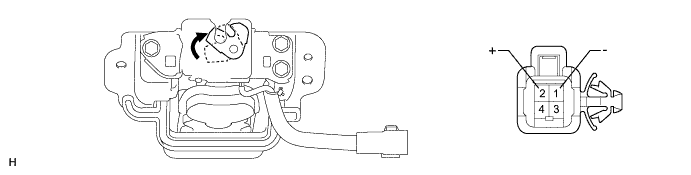
Text in Illustration 
Open - - -
Measure the resistance according to the value(s) in the table below.
Standard Resistance Tester Connection Condition Specified Condition 1 (-) - 2 (+) Open Below 1 Ω Closed 10 kΩ or higher
NG
REPLACE BACK WINDOW LOCK ASSEMBLY Click here
OK
-
-
CHECK HARNESS AND CONNECTOR (MAIN BODY ECU - BACK WINDOW LOCK ASSEMBLY AND BODY GROUND)
-
Disconnect the G64 main body ECU connector.
-
Disconnect the X4 back window lock connector.
-
Measure the resistance according to the value(s) in the table below.
Standard Resistance Tester Connection Condition Specified Condition G64-1 (GCTY) - X4-2 (+) Always Below 1 Ω G64-1 (GCTY) - Body ground Always 10 kΩ or higher X4-1 (-) - Body ground Always Below 1 Ω
NG
REPAIR OR REPLACE HARNESS OR CONNECTOR
OK
REPLACE MAIN BODY ECU (MULTIPLEX NETWORK BODY ECU) Click here
-