LIGHTING SYSTEM Door Courtesy Switch Circuit
DESCRIPTION
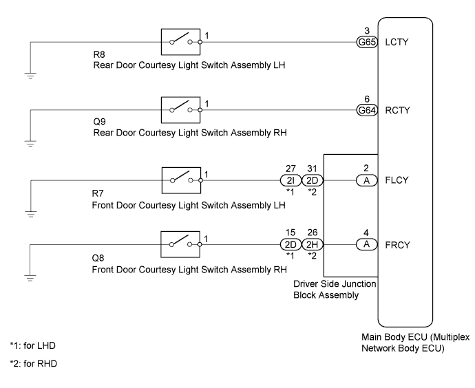
The main body ECU receives a door open/closed signal from each door courtesy light switch.
WIRING DIAGRAM
INSPECTION PROCEDURE
PROCEDURE
-
READ VALUE USING INTELLIGENT TESTER (DOOR COURTESY LIGHT SWITCH)
-
Using the intelligent tester, read the Data List Click here.
Main Body Tester Display Measurement Item/Range Normal Condition Diagnostic Note RR Door Courtesy SW* Rear door courtesy light switch RH signal / ON or OFF ON: Rear door RH open
OFF: Rear door RH closed
- RL Door Courtesy SW* Rear door courtesy light switch LH signal / ON or OFF ON: Rear door LH open
OFF: Rear door LH closed
- FR Door Courtesy Front door courtesy light switch RH signal / ON or OFF ON: Front door RH open
OFF: Front door RH closed
- FL Door Courtesy Front door courtesy light switch LH signal / ON or OFF ON: Front door LH open
OFF: Front door LH closed
-
-
*: for 5 Door
OK The display is as specified in the normal condition column. Result Result Proceed to OK A NG (Front door courtesy light switch does not operate) B NG (Rear door courtesy light switch does not operate) C -
B 
INSPECT FRONT DOOR COURTESY LIGHT SWITCH ASSEMBLY Click here
C
INSPECT REAR DOOR COURTESY LIGHT SWITCH ASSEMBLY Click here
A 
PROCEED TO NEXT SUSPECTED AREA SHOWN IN PROBLEM SYMPTOMS TABLE Click here
-
-
INSPECT FRONT DOOR COURTESY LIGHT SWITCH ASSEMBLY
-
Remove the front door courtesy light switch Click here.
-
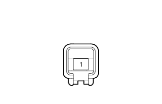
Measure the resistance according to the value(s) in the table below.
Standard Resistance Tester Connection Switch Condition Specified Condition 1 - Switch body Pin not pushed Below 1 Ω Pin pushed 10 kΩ or higher
NG 
REPLACE FRONT DOOR COURTESY LIGHT SWITCH ASSEMBLY Click here
OK 
-
-
CHECK HARNESS AND CONNECTOR (MAIN BODY ECU - FRONT DOOR COURTESY LIGHT SWITCH ASSEMBLY)
-
Remove the main body ECU Click here.
-
Disconnect the R7 or Q8 front door courtesy light switch connector.
-
Measure the resistance according to the value(s) in the table below.
Standard Resistance for LH Tester Connection Condition Specified Condition A-2 (FLCY) - R7-1 Always Below 1 Ω A-2 (FLCY) - Body ground Always 10 kΩ or higher for RH Tester Connection Condition Specified Condition A-4 (FRCY) - Q8-1 Always Below 1 Ω A-4 (FRCY) - Body ground Always 10 kΩ or higher
NG
REPAIR OR REPLACE HARNESS OR CONNECTOR
OK
-
-
CHECK DRIVER SIDE JUNCTION BLOCK ASSEMBLY
-
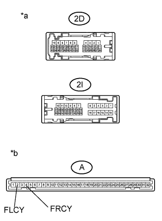
Text in Illustration *a Front view of wire harness connector
(to Driver Side Junction Block Assembly)
*b Front view of wire harness connector
(to Main Body ECU)
for LHD
-
Disconnect the 2D or 2I driver side junction block connector.
-
Remove the main body ECU Click here.
-
Measure the resistance according to the value(s) in the table.
Standard Resistance for LH Tester Connection Condition Specified Condition A-2 (FLCY) - 2I-27 Always Below 1 Ω A-2 (FLCY) - Body ground Always 10 kΩ or higher for RH Tester Connection Condition Specified Condition A-4 (FRCY) - 2D-15 Always Below 1 Ω A-4 (FRCY) - Body ground Always 10 kΩ or higher
-
-

Text in Illustration *a Front view of wire harness connector
(to Driver Side Junction Block Assembly)
*b Front view of wire harness connector
(to Main Body ECU)
for RHD
-
Disconnect the 2D or 2H driver side junction block connector.
-
Remove the main body ECU Click here.
-
Measure the resistance according to the value(s) in the table.
Standard Resistance for LH Tester Connection Condition Specified Condition A-2 (FLCY) - 2D-31 Always Below 1 Ω A-2 (FLCY) - Body ground Always 10 kΩ or higher for RH Tester Connection Condition Specified Condition A-4 (FRCY) - 2H-26 Always Below 1 Ω A-4 (FRCY) - Body ground Always 10 kΩ or higher
-
NG
REPLACE DRIVER SIDE JUNCTION BLOCK ASSEMBLY Click here
OK
REPLACE MAIN BODY ECU (MULTIPLEX NETWORK BODY ECU) Click here
-
-
INSPECT REAR DOOR COURTESY LIGHT SWITCH ASSEMBLY
-
Remove the rear door courtesy light switch Click here.
-
Measure the resistance according to the value(s) in the table below.
Standard Resistance Tester Connection Switch Condition Specified Condition 1 - Switch body Pin not pushed Below 1 Ω Pin pushed 10 kΩ or higher
NG
REPLACE REAR DOOR COURTESY LIGHT SWITCH ASSEMBLY Click here
OK
-
-
CHECK HARNESS AND CONNECTOR (MAIN BODY ECU - REAR DOOR COURTESY LIGHT SWITCH ASSEMBLY)
-
Disconnect the G64 or G65 main body ECU connector.
-
Disconnect the R8 or Q9 rear door courtesy light switch connector.
-
Measure the resistance according to the value(s) in the table below.
Standard Resistance for LH Tester Connection Condition Specified Condition G65-3 (LCTY) - R8-1 Always Below 1 Ω G65-3 (LCTY) - Body ground Always 10 kΩ or higher for RH Tester Connection Condition Specified Condition G64-6 (RCTY) - Q9-1 Always Below 1 Ω G64-6 (RCTY) - Body ground Always 10 kΩ or higher
NG
REPAIR OR REPLACE HARNESS OR CONNECTOR
OK
REPLACE MAIN BODY ECU (MULTIPLEX NETWORK BODY ECU) Click here
-