THEFT DETERRENT SYSTEM Glass Breakage Sensor Circuit
DESCRIPTION
When the glass breakage sensor detects that the back door glass, quarter window assembly LH* or quarter window assembly RH* is broken, the sensor sounds the alarm for 30 seconds.
-
*: for 5 Door
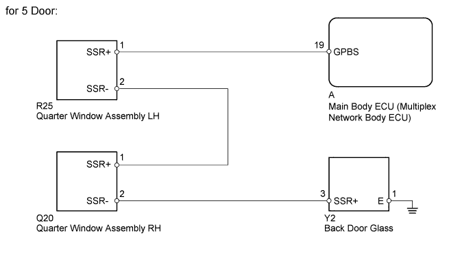
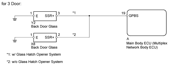
WIRING DIAGRAM
INSPECTION PROCEDURE
PROCEDURE
-
READ VALUE USING INTELLIGENT TESTER (GLASS BREAKAGE SENSOR)
-
Using the intelligent tester, read the Data List Click here.
Main Body Tester Display Measurement Item/Range Normal Condition Diagnostic Note Sealed Glas Brak Sen Glass breakage sensor detection / With or Without With: Glass breakage sensor operating
Without: Glass breakage sensor not operating
- OK "With" (glass breakage sensor operating) appears on screen. Result Result Proceed to OK A NG (for 5 Door) B NG (for 3 Door) C
B 
INSPECT QUARTER WINDOW ASSEMBLY LH (GLASS BREAKAGE SENSOR) Click here
C
INSPECT BACK DOOR GLASS (GLASS BREAKAGE SENSOR) Click here
A 
PROCEED TO NEXT SUSPECTED AREA SHOWN IN PROBLEM SYMPTOMS TABLE Click here
-
-
INSPECT QUARTER WINDOW ASSEMBLY LH (GLASS BREAKAGE SENSOR)
-
Disconnect the R25 sensor connector.
-
Measure the resistance according to the value(s) in the table below.
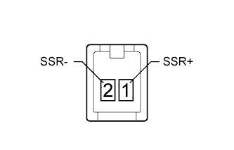
Standard Resistance Tester Connection Condition Specified Condition 1 (SSR+) - 2 (SSR-) Always Below 1 Ω
NG 
REPLACE QUARTER WINDOW ASSEMBLY LH (GLASS BREAKAGE SENSOR) Click here
OK 
-
-
INSPECT QUARTER WINDOW ASSEMBLY RH (GLASS BREAKAGE SENSOR)
-
Disconnect the Q20 sensor connector.
-
Measure the resistance according to the value(s) in the table below.
Standard Resistance Tester Connection Condition Specified Condition 1 (SSR+) - 2 (SSR-) Always Below 1 Ω
NG
REPLACE QUARTER WINDOW ASSEMBLY RH (GLASS BREAKAGE SENSOR) Click here
OK
-
-
INSPECT BACK DOOR GLASS (GLASS BREAKAGE SENSOR)
-
Disconnect the Y2 sensor connector.
-
Measure the resistance according to the value(s) in the table below.
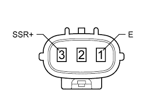
Standard Resistance Tester Connection Condition Specified Condition 3 (SSR+) - 1 (E) Always Below 1 Ω
NG
REPLACE BACK DOOR GLASS (GLASS BREAKAGE SENSOR) Click here
OK
-
-
CHECK HARNESS AND CONNECTOR (GLASS BREAKAGE SENSOR - MAIN BODY ECU AND BODY GROUND)
-
Disconnect the R25, Q20 and Y2 sensor connectors.
-
Remove the main body ECU Click here.
-
Measure the resistance according to the value(s) in the table below.
Standard Resistance Tester Connection Condition Specified Condition R25-1 (SSR+) - A-19 (GPBS) Always Below 1 Ω Q20-1 (SSR+) - R25-2 (SSR-) Always Below 1 Ω Y2-3 (SSR+) - Q20-2 (SSR-) Always Below 1 Ω R25-1 (SSR+) or A-19 (GPBS) - Body ground Always 10 kΩ or higher Q20-1 (SSR+) or R25-2 (SSR-) - Body ground Always 10 kΩ or higher Y2-3 (SSR+) or Q20-2 (SSR-) - Body ground Always 10 kΩ or higher Y2-1 (E) - Body ground Always Below 1 Ω
NG
REPAIR OR REPLACE HARNESS OR CONNECTOR
OK
REPLACE MAIN BODY ECU (MULTIPLEX NETWORK BODY ECU) Click here
-
-
INSPECT BACK DOOR GLASS (GLASS BREAKAGE SENSOR)
-
w/ Glass Hatch Opener System:
-
Disconnect the Y2 sensor connector.
-
Measure the resistance according to the value(s) in the table below.
Standard Resistance Tester Connection Condition Specified Condition 3 (SSR+) - 1 (E) Always Below 1 Ω
-
-
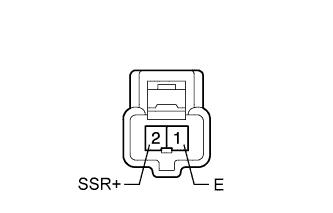
w/o Glass Hatch Opener System:
-
Disconnect the X8 sensor connector.
-
Measure the resistance according to the value(s) in the table below.
Standard Resistance Tester Connection Condition Specified Condition 2 (SSR+) - 1 (E) Always Below 1 Ω Result Result Proceed to OK A NG (w/ Glass Hatch Opener System) B NG (w/o Glass Hatch Opener System) C
-
B
REPLACE BACK DOOR GLASS (GLASS BREAKAGE SENSOR) Click here
C
REPLACE BACK DOOR GLASS (GLASS BREAKAGE SENSOR) Click here
A
-
-
CHECK HARNESS AND CONNECTOR (GLASS BREAKAGE SENSOR - MAIN BODY ECU AND BODY GROUND)
-
w/ Glass Hatch Opener System:
-
Disconnect the Y2 sensor connector.
-
Remove the main body ECU Click here.
Standard Resistance Tester Connection Condition Specified Condition Y2-3 (SSR+) - A-19 (GPBS) Always Below 1 Ω Y2-3 (SSR+) or A-19 (GPBS) - Body ground Always 10 kΩ or higher Y2-1 (E) - Body ground Always Below 1 Ω
-
-
w/o Glass Hatch Opener System:
-
Disconnect the X8 sensor connector.
-
Remove the main body ECU Click here.
Standard Resistance Tester Connection Condition Specified Condition X8-2 (SSR+) - A-19 (GPBS) Always Below 1 Ω X8-2 (SSR+) or A-19 (GPBS) - Body ground Always 10 kΩ or higher X8-1 (E) - Body ground Always Below 1 Ω
-
NG
REPAIR OR REPLACE HARNESS OR CONNECTOR
OK
REPLACE MAIN BODY ECU (MULTIPLEX NETWORK BODY ECU) Click here
-