ENGINE IMMOBILISER SYSTEM (w/o Entry and Start System) TERMINALS OF ECU

-
CHECK TRANSPONDER KEY AMPLIFIER

-
Disconnect the G75 amplifier connector.
-
Measure the resistance according to the value(s) in the table below.
Terminal No. (Symbol) Wiring Color Terminal Description Condition Specified Condition G75-7 (AGND) - Body ground L - Body ground Ground Always Below 1 Ω If the result is not as specified, there may be a malfunction on the wire harness side.
-
Reconnect the G75 amplifier connector.
-
Measure the voltage according to the value(s) in the table below.
Terminal No. (Symbol) Wiring Color Terminal Description Condition Specified Condition G75-1 (VC5) - G75-7 (AGND) R - L Power supply No key in ignition key cylinder Below 1 V Key inserted in ignition key cylinder 4.6 to 5.4 V G75-4 (CODE) - G75-7 (AGND) LG - L Demodulated signal of key code data No key in ignition key cylinder Below 1 V Key inserted in ignition key cylinder Pulse generation (see waveform 1) G75-5 (TXCT) - G75-7 (AGND) P - L Key code output signal No key in ignition key cylinder Below 1 V Key inserted in ignition key cylinder Pulse generation (see waveform 2) If the result is not as specified, the amplifier may have a malfunction.
-

Inspect using an oscilloscope.
-
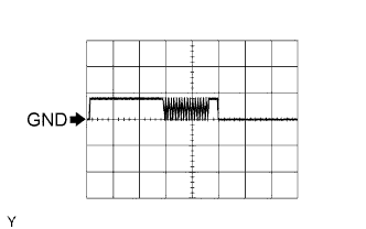
Waveform 1 (Reference)
Measurement Condition Item Content Tester Connection G75-4 (CODE) - G75-7 (AGND) Tool Setting 5 V/DIV., 20 ms./DIV. Condition Key inserted in ignition key cylinder -

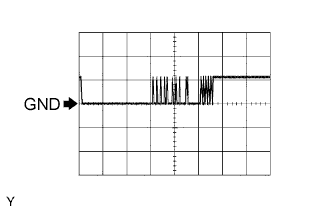
Waveform 2 (Reference)
Measurement Condition Item Content Tester Connection G75-5 (TXCT) - G75-7 (AGND) Tool Setting 5 V/DIV., 20 ms./DIV. Condition Key inserted in ignition key cylinder
-
-
-
CHECK TRANSPONDER KEY ECU ASSEMBLY (for 5L-E)

-
Disconnect the G138 ECU connector.
-
Measure the resistance and voltage according to the value(s) in the table below.
Terminal No. (Symbol) Wiring Color Terminal Description Condition Specified Condition G138-16 (GND) - Body ground W-B - Body ground Ground Always Below 1 Ω G138-1 (+B) - G138-16 (GND) P - W-B Battery Always 11 to 14 V G138-2 (IG) - G138-16 (GND) W - W-B Ignition switch Ignition switch off Below 1 V Ignition switch ON 11 to 14 V G138-3 (KSW) - G138-16 (GND) G - W-B Unlock warning switch No key in ignition key cylinder 10 kΩ or higher Key inserted in ignition key cylinder Below 1 Ω If the result is not as specified, there may be a malfunction on the wire harness side.
-
Reconnect the G138 ECU connector.
-
Measure the resistance and voltage according to the value(s) in the table below.
Terminal No. (Symbol) Wiring Color Terminal Description Condition Specified Condition G138-14 (VC5) - G138-16 (GND) R - W-B Power source No key in ignition key cylinder Below 1 V Key inserted in ignition key cylinder 4.6 to 5.4 V G138-7 (CTY) - G138-16 (GND) R - W-B*1
B - W-B*2
Front door courtesy light switch (for Driver Side) Driver door closed 10 kΩ or higher Driver door open Below 1 Ω G138-4 (TXCT) - G138-16 (GND) P - W-B Transponder key amplifier communication signal No key in ignition key cylinder Below 1 V Key inserted in ignition key cylinder Pulse generation (see waveform 1) G138-15 (CODE) - G138-16 (GND) LG - W-B Transponder key amplifier communication signal No key in ignition key cylinder Below 1 V Key inserted in ignition key cylinder Pulse generation (see waveform 2) G138-13 (EFIO) - G138-16 (GND) W - W-B ECM output signal Ignition switch off Below 1 V Ignition switch ON Pulse generation (see waveform 3) G138-12 (EFII) - G138-16 (GND) SB - W-B ECM input signal Within 3 seconds after starter operates and initial combustion occurs, or within 3 seconds after ignition switch first turned to ON after battery disconnected and connected Pulse generation (see waveform 4) G138-8 (IND) - G138-16 (GND) G - W-B Security indicator light signal Immobiliser set Alternating between 11 to 14 V and below 1 V Immobiliser unset Below 1 V G138-9 (D) - G138-16 (GND) W - W-B Diagnosis tester communication Always Pulse generation G138-5 (AGND) - Body ground L - Body ground Ground Always Below 1 Ω
-
*1: for LHD
-
*2: for RHD
If the result is not as specified, the ECU may have a malfunction.
-
-
Inspect using an oscilloscope.
-
Waveform 1 (Reference)
Measurement Condition Item Content Tester Connection G138-4 (TXCT) - G138-16 (GND) Tool Setting 5 V/DIV., 20 ms./DIV. Condition Key inserted in ignition key cylinder -
Waveform 2 (Reference)
Measurement Condition Item Content Tester Connection G138-15 (CODE) - G138-16 (GND) Tool Setting 5 V/DIV., 20 ms./DIV. Condition Key inserted in ignition key cylinder -
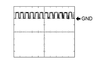
Waveform 3 (Reference)
Measurement Condition Item Content Tester Connection G138-13 (EFIO) - G138-16 (GND) Tool Setting 10 V/DIV., 100 ms./DIV. Condition Ignition switch ON -
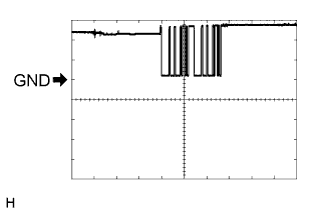
Waveform 4 (Reference)
Measurement Condition Item Content Tester Connection G138-12 (EFII) - G138-16 (GND) Tool Setting 5 V/DIV., 500 ms./DIV. Condition Within 3 seconds after starter operates and initial combustion occurs, or within 3 seconds after ignition switch first turned to ON after battery disconnected and connected
-
-
-
CHECK TRANSPONDER KEY ECU ASSEMBLY (except 5L-E)

-
Disconnect the G74 ECU connector.
-
Measure the resistance and voltage according to the value(s) in the table below.
Terminal No. (Symbol) Wiring Color Terminal Description Condition Specified Condition G74-16 (GND) - Body ground W-B - Body ground Ground Always Below 1 Ω G74-1 (+B) - G74-16 (GND) P - W-B Battery Always 11 to 14 V G74-2 (IG) - G74-16 (GND) W - W-B Ignition switch Ignition switch off Below 1 V Ignition switch ON 11 to 14 V G74-3 (KSW) - G74-16 (GND) G - W-B Unlock warning switch No key in ignition key cylinder 10 kΩ or higher Key inserted in ignition key cylinder Below 1 Ω If the result is not as specified, there may be a malfunction on the wire harness side.
-
Reconnect the G74 ECU connector.
-
Measure the resistance and voltage according to the value(s) in the table below.
Terminal No. (Symbol) Wiring Color Terminal Description Condition Specified Condition G74-14 (VC5) - G74-16 (GND) R - W-B Power source No key in ignition key cylinder Below 1 V Key inserted in ignition key cylinder 4.6 to 5.4 V G74-7 (CTY) - G74-16 (GND) R - W-B*1
B - W-B*2
Front door courtesy light switch (for Driver Side) Driver door closed 10 kΩ or higher Driver door open Below 1 Ω G74-4 (TXCT) - G74-16 (GND) P - W-B Transponder key amplifier communication signal No key in ignition key cylinder Below 1 V Key inserted in ignition key cylinder Pulse generation (see waveform 1) G74-15 (CODE) - G74-16 (GND) LG - W-B Transponder key amplifier communication signal No key in ignition key cylinder Below 1 V Key inserted in ignition key cylinder Pulse generation (see waveform 2) G74-13 (EFIO) - G74-16 (GND) W - W-B ECM output signal Ignition switch off Below 1 V Ignition switch ON Pulse generation (see waveform 3) G74-12 (EFII) - G74-16 (GND) SB - W-B ECM input signal Within 3 seconds after starter operates and initial combustion occurs, or within 3 seconds after ignition switch first turned to ON after battery disconnected and connected Pulse generation (see waveform 4) G74-8 (IND) - G74-16 (GND) G - W-B Security indicator light signal Immobiliser set Alternating between 11 to 14 V and below 1 V Immobiliser unset Below 1 V G74-9 (D) - G74-16 (GND) W - W-B Diagnosis tester communication Always Pulse generation G74-5 (AGND) - Body ground L - Body ground Ground Always Below 1 Ω
-
*1: for LHD
-
*2: for RHD
If the result is not as specified, the ECU may have a malfunction.
-
-
Inspect using an oscilloscope.
-
Waveform 1 (Reference)
Measurement Condition Item Content Tester Connection G74-4 (TXCT) - G74-16 (GND) Tool Setting 5 V/DIV., 20 ms./DIV. Condition Key inserted in ignition key cylinder -
Waveform 2 (Reference)
Measurement Condition Item Content Tester Connection G74-15 (CODE) - G74-16 (GND) Tool Setting 5 V/DIV., 20 ms./DIV. Condition Key inserted in ignition key cylinder -
Waveform 3 (Reference)
Measurement Condition Item Content Tester Connection G74-13 (EFIO) - G74-16 (GND) Tool Setting 10 V/DIV., 100 ms./DIV. Condition Ignition switch ON -
Waveform 4 (Reference)
Measurement Condition Item Content Tester Connection G74-12 (EFII) - G74-16 (GND) Tool Setting 5 V/DIV., 500 ms./DIV. Condition Within 3 seconds after starter operates and initial combustion occurs, or within 3 seconds after ignition switch first turned to ON after battery disconnected and connected
-
-
-
CHECK ECM (for 2TR-FE)

-
Measure the voltage according to the value(s) in the table below.
Terminal No. (Symbol) Wiring Color Terminal Description Condition Specified Condition G60-32 (IMO) - Body ground SB - Body ground Transponder key ECU output signal Within 3 seconds after starter operates and initial combustion occurs, or within 3 seconds after ignition switch first turned to ON after battery disconnected and connected Pulse generation
(see waveform 1)
G60-31 (IMI) - Body ground W - Body ground Transponder key ECU input signal Ignition switch off → ON Below 1 V → Pulse generation
(see waveform 2)
If the result is not as specified, the ECM may have a malfunction.
-
Inspect using an oscilloscope.
-
Waveform 1 (Reference)
Measurement Condition Item Content Tester Connection G60-32 (IMO) - Body ground Tool Setting 5 V/DIV., 500 ms./DIV. Condition Within 3 seconds after starter operates and initial combustion occurs, or within 3 seconds after ignition switch first turned to ON after battery disconnected and connected -
Waveform 2 (Reference)
Measurement Condition Item Content Tester Connection G60-31 (IMI) - Body ground Tool Setting 10 V/DIV., 100 ms./DIV. Condition Ignition switch ON
-
-
-
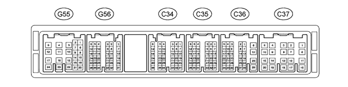
CHECK ECM (for 1GR-FE)
-
Measure the voltage according to the value(s) in the table below.
Terminal No. (Symbol) Wiring Color Terminal Description Condition Specified Condition G56-20 (IMO) - Body ground SB - Body ground Transponder key ECU output signal Within 3 seconds after starter operates and initial combustion occurs, or within 3 seconds after ignition switch first turned to ON after battery disconnected and connected Pulse generation
(see waveform 1)
G56-14 (IMI) - Body ground W - Body ground Transponder key ECU input signal Ignition switch off → ON Below 1 V → Pulse generation
(see waveform 2)
If the result is not as specified, the ECM may have a malfunction.
-
Inspect using an oscilloscope.
-
Waveform 1 (Reference)
Measurement Condition Item Content Tester Connection G56-20 (IMO) - Body ground Tool Setting 5 V/DIV., 500 ms./DIV. Condition Within 3 seconds after starter operates and initial combustion occurs, or within 3 seconds after ignition switch first turned to ON after battery disconnected and connected -
Waveform 2 (Reference)
Measurement Condition Item Content Tester Connection G56-14 (IMI) - Body ground Tool Setting 10 V/DIV., 100 ms./DIV. Condition Ignition switch ON
-
-
-
CHECK ECM (for 1KD-FTV)

-
Measure the voltage according to the value(s) in the table below.
Terminal No. (Symbol) Wiring Color Terminal Description Condition Specified Condition G58-29 (IMO) - Body ground SB - Body ground Transponder key ECU output signal Within 3 seconds after starter operates and initial combustion occurs, or within 3 seconds after ignition switch first turned to ON after battery disconnected and connected Pulse generation
(see waveform 1)
G58-28 (IMI) - Body ground W - Body ground Transponder key ECU input signal Ignition switch off → ON Below 1 V → Pulse generation
(see waveform 2)
If the result is not as specified, the ECM may have a malfunction.
-
Inspect using an oscilloscope.
-
Waveform 1 (Reference)
Measurement Condition Item Content Tester Connection G58-29 (IMO) - Body ground Tool Setting 5 V/DIV., 500 ms./DIV. Condition Within 3 seconds after starter operates and initial combustion occurs, or within 3 seconds after ignition switch first turned to ON after battery disconnected and connected -
Waveform 2 (Reference)
Measurement Condition Item Content Tester Connection G58-28 (IMI) - Body ground Tool Setting 10 V/DIV., 100 ms./DIV. Condition Ignition switch ON
-
-
-
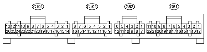
CHECK ECM (for 5L-E)
-
Measure the voltage according to the value(s) in the table below.
Terminal No. (Symbol) Wiring Color Terminal Description Condition Specified Condition G61-6 (IMO) - Body ground SB - Body ground Transponder key ECU output signal Within 3 seconds after starter operates and initial combustion occurs, or within 3 seconds after ignition switch first turned to ON after battery disconnected and connected Pulse generation
(see waveform 1)
G61-17 (IMI) - Body ground W - Body ground Transponder key ECU input signal Ignition switch off → ON Below 1 V → Pulse generation
(see waveform 2)
If the result is not as specified, the ECM may have a malfunction.
-
Inspect using an oscilloscope.
-
Waveform 1 (Reference)
Measurement Condition Item Content Tester Connection G61-6 (IMO) - Body ground Tool Setting 5 V/DIV., 500 ms./DIV. Condition Within 3 seconds after starter operates and initial combustion occurs, or within 3 seconds after ignition switch first turned to ON after battery disconnected and connected -
Waveform 2 (Reference)
Measurement Condition Item Content Tester Connection G61-17 (IMI) - Body ground Tool Setting 10 V/DIV., 100 ms./DIV. Condition Ignition switch ON
-
-