ENTRY AND START SYSTEM (for Start Function) TERMINALS OF ECU

-
CHECK POWER MANAGEMENT CONTROL ECU
-
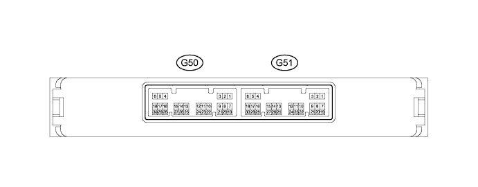
Disconnect the G51 power management control ECU connector.
-
Measure the voltage and resistance according to the value(s) in the table below.
Terminal No. (Symbol) Wiring Color Terminal Description Condition Specified Condition G51-1 (AM22) - Body ground B - Body ground +B power supply Always 9.5 to 14 V G51-2 (AM21) - Body ground B - Body ground +B power supply Always 9.5 to 14 V G51-5 (GND2) - Body ground W-B - Body ground Ground Always Below 1 Ω G51-6 (GND) - Body ground W-B - Body ground Ground Always Below 1 Ω G51-17 (SSW2) - Body ground R - Body ground Engine switch signal Engine switch pushed Below 1 Ω G51-17 (SSW2) - Body ground R - Body ground Engine switch signal Engine switch not pushed 10 kΩ or higher G51-18 (SSW1) - Body ground LG - Body ground Engine switch signal Engine switch pushed Below 1 Ω G51-18 (SSW1) - Body ground LG - Body ground Engine switch signal Engine switch not pushed 10 kΩ or higher G51-24 (LIN2) - Body ground G - Body ground LIN line Always 10 kΩ or higher If the result is not as specified, there may be a malfunction on the wire harness side.
-
Reconnect the G51 power management control ECU connector.
-
Measure the voltage according to the value(s) in the table below.
Terminal No. (Symbol) Wiring Color Terminal Description Condition Specified Condition G51-3 (SLP) - G51-6 (GND) SB - W-B Steering lock actuator position signal Steering lock released Pulse generation
(See waveform 1)
G51-3 (SLP) - G51-6 (GND) SB - W-B Steering lock actuator position signal Steering lock locked Pulse generation
(See waveform 1)
G51-8 (SLR+) - G51-6 (GND) W - W-B Steering lock motor signal Steering lock motor operating Below 1 V G51-8 (SLR+) - G51-6 (GND) W - W-B Steering lock motor signal Steering lock motor not operating 11 to 14 V G51-10 (INDW) - G51-6 (GND) L - W-B Warning signal
-
Clutch pedal depressed
-
Engine switch on (ACC) or on (IG)
for Manual Transmission:
-
Brake pedal depressed
-
Shift lever in P
-
Engine switch on (ACC) or on (IG)
for Automatic Transmission:
8 to 14 V G51-16 (P) - G51-6 (GND) V - W-B Shift lock signal Shift lever in P*1 8 to 14 V G51-16 (P) - G51-6 (GND) V - W-B Shift lock signal Shift lever not in P*1 Below 1 V G51-19 (ACCD) - G51-6 (GND) R - W-B ACC signal Engine switch on (ACC) 8 to 14 V G51-19 (ACCD) - G51-6 (GND) R - W-B ACC signal Engine switch off Below 1 V G51-20 (IG1D) - G51-6 (GND) V - W-B IG1 signal Engine switch on (IG) 8 to 14 V G51-20 (IG1D) - G51-6 (GND) V - W-B IG1 signal Engine switch on (ACC) Below 1 V G51-22 (INDS) - G51-6 (GND) B - W-B Vehicle condition signal
-
Clutch pedal depressed
for Manual Transmission:
-
Brake pedal depressed
-
Shift lever in P
for Automatic Transmission:
8 to 14 V G51-23 (SPD) - G51-6 (GND) R - W-B Vehicle speed signal Engine switch on (IG), vehicle being driven at approx. 20 km/h (12 mph) Pulse generation
(See waveform 2)
G50-2 (STA) - G51-6 (GND) W - W-B Park/neutral position switch*1 or clutch start switch*2 signal
-
Clutch pedal depressed
for Manual Transmission:
-
Shift lever in P or N
for Automatic Transmission:
Below 1 V G50-3 (STAR) - G51-6 (GND) B - W-B Starter signal
-
Clutch pedal depressed
-
Engine cranking
for Manual Transmission:
-
Brake pedal depressed
-
Shift lever in P
-
Engine cranking
for Automatic Transmission:
8 to 14 V*3 G50-8 (IG2D) - G51-6 (GND) L - W-B IG2 signal Engine switch on (IG) 8 to 14 V G50-8 (IG2D) - G51-6 (GND) L - W-B IG2 signal Engine switch on (ACC) Below 1 V G50-11 (STP1) - G51-6 (GND) V - W-B Stop light signal Brake pedal depressed*1 8 to 14 V G50-11 (STP1) - G51-6 (GND) V - W-B Stop light signal Brake pedal released*1 Below 1 V
-
*1: for Automatic Transmission
-
*2: for Manual Transmission
-
*3: Voltage is output for 0.3 seconds when the engine is cranking. Disconnect the connector from the ECM before measuring the voltage.
If the result is not as specified, the ECU may have a malfunction.
-
-
Using an oscilloscope, check the signal waveform of the ECU.
-
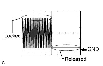
Waveform 1
Waveform 1 (Reference) Terminal No. (Symbol) G51-3 (SLP) - G51-6 (GND) Tool Setting 2 V/DIV., 100 ms./DIV. Vehicle Condition Steering lock locked or released -
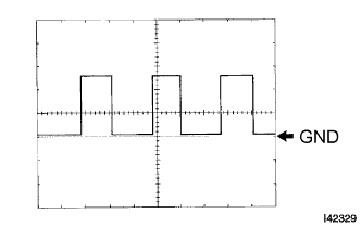
Waveform 2
Waveform 2 (Reference) Terminal No. (Symbol) G51-23 (SPD) - G51-6 (GND) Tool Setting 5 V/DIV., 10 ms./DIV. Vehicle Condition Engine switch on (IG), vehicle being driven at approx. 5 km/h (3 mph) Tech Tips
As the vehicle speed increases, the wavelength shortens.
-
-
-
CHECK CERTIFICATION ECU
-
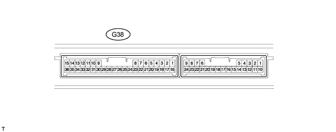
Disconnect the G38 certification ECU connector.
-
Measure the voltage and resistance according to the value(s) in the table below.
Terminal No. (Symbol) Wiring Color Terminal Description Condition Specified Condition G38-1 (+B) - Body ground V - Body ground +B power supply Always 11 to 14 V G38-15 (E) - Body ground W-B - Body ground Ground Always Below 1 Ω G38-29 (LIN) - Body ground G - Body ground LIN line Always 10 kΩ or higher If the result is not as specified, there may be a malfunction on the wire harness side.
-
-
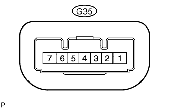
CHECK STEERING LOCK ECU
-
Disconnect the G35 steering lock ECU connector.
-
Measure the voltage and resistance according to the value(s) in the table below.
Terminal No. (Symbol) Wiring Color Terminal Description Condition Specified Condition G35-1 (GND) - Body ground W-B - Body ground Ground Always Below 1 Ω G35-6 (IG2) - Body ground W - Body ground Ignition power supply Engine switch on (IG) 11 to 14 V G35-6 (IG2) - Body ground W - Body ground Ignition power supply Engine switch off Below 1 V G35-7 (B) - Body ground G - Body ground +B power supply Always 11 to 14 V
-
If the result is not as specified, there may be a malfunction on the wire harness side.
-
-
Reconnect the G35 steering lock ECU connector.
-
Measure the voltage according to the value(s) in the table below.
Terminal No. (Symbol) Wiring Color Terminal Description Condition Specified Condition G35-4 (SLP1) - G35-1 (GND) SB - W-B Steering lock actuator position signal Steering lock locked 11 to 14 V G35-4 (SLP1) - G35-1 (GND) SB - W-B Steering lock actuator position signal Steering lock released Below 1 V
-
If the result is not as specified, the ECU may have a malfunction.
-
-