ENTRY AND START SYSTEM (for Entry Function) Room Oscillator does not Recognize Key
DESCRIPTION
If the room oscillator does not recognize the key, one of the following may be the cause: 1) communication between the indoor No. 1 electrical key antenna (front floor) and electrical key transmitter cannot be performed; 2) communication between the indoor No. 2 electrical key antenna (rear floor) and electrical key transmitter cannot be performed; or 3) communication between the indoor No. 3 electrical key antenna (inside luggage) and electrical key transmitter cannot be performed.
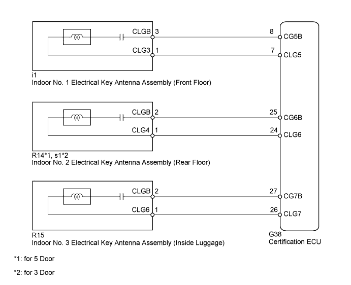
WIRING DIAGRAM
INSPECTION PROCEDURE
Note
-
The entry and start system (for Entry Function) uses a multiplex communication system (LIN communication system) and the CAN communication system. Inspect the communication function by following How to Proceed with Troubleshooting Click here. Troubleshoot the entry and start system (for Entry Function) after confirming that the communication systems are functioning properly.
-
When using the intelligent tester with the engine switch off to troubleshoot: Connect the intelligent tester to the vehicle and turn a courtesy light switch on and off at 1.5 second intervals until communication between the intelligent tester and vehicle begins.
-
Before replacing the certification ECU, refer to the Service Bulletin.
PROCEDURE
-
CHECK ENTRY AND START SYSTEM (START FUNCTION)
-
Text in Illustration *1 Engine Switch *2 Electrical Key Transmitter Remove the battery of the electrical key transmitter Click here.
-
With the clutch pedal (for Manual Transmission) or brake pedal (for Automatic Transmission) depressed, touch the key to the engine switch.
-
When operating the engine switch, check whether the power source mode changes.
Tech Tips
-
When the electrical key transmitter cannot be verified even though it is in the operating range of the start function, the engine start check can be performed by removing the transmitter battery from the electrical key transmitter and holding the transmitter against the engine switch.
-
When performing the check, if the power source mode changes, there is a problem with key certification inside the cabin.
OK Power source mode changes. -
NG 
GO TO ENTRY AND START SYSTEM (FOR START FUNCTION) Click here
OK 
-
-
CHECK WAVE ENVIRONMENT
-
Install the battery to the electrical key transmitter Click here.
-
Move the electrical key transmitter as described below and perform the operation inspection Click here.
-
Bring the electrical key transmitter near the indoor No. 1 electrical key antenna (front floor) and perform an engine control system start check.
Note
If the key is brought within 0.2 m (0.656 ft.) of the indoor No. 1 electrical key antenna (front floor), communication is not possible.
-
Bring the electrical key transmitter near the indoor No. 2 electrical key antenna (rear floor) and perform an engine control system start check.
Note
If the key is brought within 0.2 m (0.656 ft.) of the indoor No. 2 electrical key antenna (rear floor), communication is not possible.
-
Bring the electrical key transmitter near the indoor No. 3 electrical key antenna (inside luggage) and perform an engine control system start check.
Note
If the key is brought within 0.2 m (0.656 ft.) of the indoor No. 3 electrical key antenna (rear floor), communication is not possible.
Tech Tips
-
When the electrical key transmitter is brought near the indoor electrical key antenna, the possibility of wave interference decreases, and it can be determined if wave interference is causing the problem symptom.
-
If the inspection result is that the operation check is normal, the possibility of wave interference is high. Also, added vehicle components may cause wave interference. If installed, remove them and perform the operation check.
OK Engine can be started. -
-
NG 
CHECK ELECTRICAL KEY ANTENNAS IN KEY DIAGNOSTIC MODE Click here
OK 
AFFECTED BY WAVE INTERFERENCE
-
-
CHECK ELECTRICAL KEY ANTENNAS IN KEY DIAGNOSTIC MODE
-
Check the following antennas in the key diagnostic mode Click here.
-
Check the indoor No. 1 electrical key antenna (front floor).
When the electrical key transmitter is at the inspection point, check that the wireless door lock buzzer sounds.
-
Check the indoor No. 2 electrical key antenna (rear floor.
When the electrical key transmitter is at the inspection point, check that the wireless door lock buzzer sounds.
-
Check the indoor No. 3 electrical key antenna (inside luggage).
When the electrical key transmitter is at the inspection point, check that the wireless door lock buzzer sounds.
Tech Tips
-
If the buzzer sounds, it can be determined that the vehicle interior transmitters are operating normally.
-
It is possible to check which indoor electrical key antenna (front floor, rear floor or inside luggage) is operating by the sounding of the buzzer.
-
If the buzzer does not sound for any indoor electrical key antennas, the certification ECU circuit may have a malfunction.
OK Wireless door lock buzzer sounds. Result Result Proceed to Front operation check fails A Rear operation check fails B Luggage operation check fails C Front, rear and luggage operation checks are normal D -
-
B
CHECK HARNESS AND CONNECTOR (INDOOR NO. 2 ELECTRICAL KEY ANTENNA - CERTIFICATION ECU) Click here
C
CHECK HARNESS AND CONNECTOR (INDOOR NO. 3 ELECTRICAL KEY ANTENNA - CERTIFICATION ECU) Click here
D
REPLACE CERTIFICATION ECU
A
-
-
CHECK HARNESS AND CONNECTOR (INDOOR NO. 1 ELECTRICAL KEY ANTENNA - CERTIFICATION ECU)
-
Disconnect the i1 antenna connector.
-
Disconnect the G38 ECU connector.
-
Measure the resistance according to the value(s) in the table below.
Standard Resistance Tester Connection Condition Specified Condition i1-1 (CLG3) - G38-7 (CLG5) Always Below 1 Ω i1-3 (CLGB) - G38-8 (CG5B) Always Below 1 Ω G38-7 (CLG5) - Body ground Always 10 kΩ or higher G38-8 (CG5B) - Body ground Always 10 kΩ or higher
NG
REPAIR OR REPLACE HARNESS OR CONNECTOR
OK
-
-
CHECK CERTIFICATION ECU (OUTPUT SIGNAL)
-
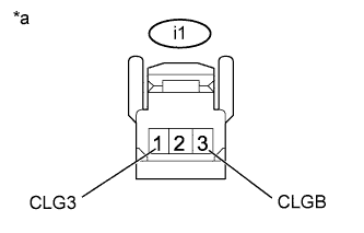
Text in Illustration *a Front view of wire harness connector
(to Indoor No. 1 Electrical Key Antenna [Front Floor])
Disconnect the i1 antenna connector.
-
Measure the voltage according to the value(s) in the table below.
OK Tester Connection Switch Condition Specified Condition i1-1 (CLG3) - i1-3 (CLGB) Engine switch off, all doors closed, key not in cabin and lock sensor off → on No pulse generation → pulse generation
NG
REPLACE CERTIFICATION ECU
OK
-
-
REPLACE INDOOR NO. 1 ELECTRICAL KEY ANTENNA ASSEMBLY (FRONT FLOOR)
-
Temporarily replace the indoor No. 1 electrical key antenna (front floor) with a new or normally functioning one Click here.
NEXT
-
-
CHECK ELECTRICAL KEY ANTENNA IN KEY DIAGNOSTIC MODE
-
Check the following antenna in the key diagnostic mode Click here.
-
Check the indoor No. 1 electrical key antenna (front floor).
When the electrical key transmitter is at the inspection point, check that the wireless door lock buzzer sounds.
OK Wireless door lock buzzer sounds.
-
NG
REPLACE CERTIFICATION ECU
OK
END (INDOOR NO. 1 ELECTRICAL KEY ANTENNA ASSEMBLY IS DEFECTIVE)
-
-
CHECK HARNESS AND CONNECTOR (INDOOR NO. 2 ELECTRICAL KEY ANTENNA - CERTIFICATION ECU)
-
Disconnect the R14*1 or s1*2 antenna connector.
-
*1: for 5 Door
-
*2: for 3 Door
-
-
Disconnect the G38 ECU connector.
-
Measure the resistance according to the value(s) in the table below.
Standard Resistance for 5 Door Tester Connection Condition Specified Condition R14-1 (CLG4) - G38-24 (CLG6) Always Below 1 Ω R14-2 (CLGB) - G38-25 (CG6B) Always Below 1 Ω G38-24 (CLG6) - Body ground Always 10 kΩ or higher G38-25 (CG6B) - Body ground Always 10 kΩ or higher for 3 Door Tester Connection Condition Specified Condition s1-1 (CLG4) - G38-24 (CLG6) Always Below 1 Ω s1-2 (CLGB) - G38-25 (CG6B) Always Below 1 Ω G38-24 (CLG6) - Body ground Always 10 kΩ or higher G38-25 (CG6B) - Body ground Always 10 kΩ or higher
NG
REPAIR OR REPLACE HARNESS OR CONNECTOR
OK
-
-
CHECK CERTIFICATION ECU (OUTPUT SIGNAL)
-
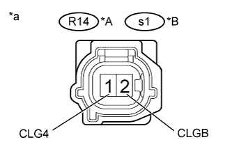
Text in Illustration *A for 5 Door *B for 3 Door *a Front view of wire harness connector
(to Indoor No. 2 Electrical Key Antenna [Rear Floor])
Disconnect the R14*1 or s1*2 antenna connector.
-
*1: for 5 Door
-
*2: for 3 Door
-
-
Measure the voltage according to the value(s) in the table below.
OK for 5 Door Tester Connection Switch Condition Specified Condition R14-1 (CLG4) - R14-2 (CLGB) Engine switch off, all doors closed, key not in cabin and lock sensor off → on No pulse generation → pulse generation for 3 Door Tester Connection Switch Condition Specified Condition s1-1 (CLG4) - s1-2 (CLGB) Engine switch off, all doors closed, key not in cabin and lock sensor off → on No pulse generation → pulse generation
NG
REPLACE CERTIFICATION ECU
OK
-
-
REPLACE INDOOR NO. 2 ELECTRICAL KEY ANTENNA ASSEMBLY (REAR FLOOR)
-
Temporarily replace the indoor No. 2 electrical key antenna (rear floor) with a new or normally functioning one Click here.
NEXT
-
-
CHECK ELECTRICAL KEY ANTENNA IN KEY DIAGNOSTIC MODE
-
Check the following antenna in the key diagnostic mode Click here.
-
Check the indoor No. 2 electrical key antenna (rear floor).
When the electrical key transmitter is at the inspection point, check that the wireless door lock buzzer sounds.
OK Wireless door lock buzzer sounds.
-
NG
REPLACE CERTIFICATION ECU
OK
END (INDOOR NO. 2 ELECTRICAL KEY ANTENNA ASSEMBLY IS DEFECTIVE)
-
-
CHECK HARNESS AND CONNECTOR (INDOOR NO. 3 ELECTRICAL KEY ANTENNA - CERTIFICATION ECU)
-
Disconnect the R15 antenna connector.
-
Disconnect the G38 ECU connector.
-
Measure the resistance according to the value(s) in the table below.
Standard Resistance Tester Connection Condition Specified Condition R15-1 (CLG6) - G38-26 (CLG7) Always Below 1 Ω R15-2 (CLGB) - G38-27 (CG7B) Always Below 1 Ω G38-26 (CLG7) - Body ground Always 10 kΩ or higher G38-27 (CG7B) - Body ground Always 10 kΩ or higher
NG
REPAIR OR REPLACE HARNESS OR CONNECTOR
OK
-
-
CHECK CERTIFICATION ECU (OUTPUT SIGNAL)
-
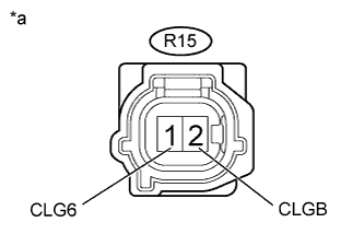
Text in Illustration *a Front view of wire harness connector
(to Indoor No. 3 Electrical Key Antenna [Inside Luggage])
Disconnect the R15 antenna connector.
-
Measure the voltage according to the value(s) in the table below.
OK Tester Connection Switch Condition Specified Condition R15-1 (CLG6) - R15-2 (CLGB) Engine switch off, all doors closed, key not in cabin and lock sensor off → on No pulse generation → pulse generation
NG
REPLACE CERTIFICATION ECU
OK
-
-
REPLACE INDOOR NO. 3 ELECTRICAL KEY ANTENNA ASSEMBLY (INSIDE LUGGAGE)
-
Temporarily replace the indoor No. 3 electrical key antenna (inside luggage) with a new or normally functioning one Click here.
NEXT
-
-
CHECK ELECTRICAL KEY ANTENNA IN KEY DIAGNOSTIC MODE
-
Check the following antenna in the key diagnostic mode Click here.
-
Check the indoor No. 3 electrical key antenna (inside luggage).
When the electrical key transmitter is at the inspection point, check that the wireless door lock buzzer sounds.
OK Wireless door lock buzzer sounds.
-
NG
REPLACE CERTIFICATION ECU
OK
END (INDOOR NO. 3 ELECTRICAL KEY ANTENNA ASSEMBLY IS DEFECTIVE)
-