FRONT DOOR LOCK INSTALLATION

Tech Tips
-
Use the same procedure for the RH and LH sides.
-
The procedure listed below is for the LH side.
-
INSTALL FRONT DOOR INSIDE LOCKING CABLE ASSEMBLY LH
-
Install the front door inside locking cable assembly.
-
Attach the 3 claws.
-
-
INSTALL FRONT DOOR LOCK REMOTE CONTROL CABLE ASSEMBLY LH
-
Install the front door lock remote control cable assembly.
-
-
INSTALL FRONT DOOR LOCK ASSEMBLY LH
Note
-
When reusing the removed front door lock assembly, replace the door lock wiring harness seal on the connector with a new one.
-
Do not allow grease or dust to adhere to the surface of the connector which contacts the door lock wiring harness seal.
-
Reusing the door lock wiring harness seal or using a damaged door lock wiring harness seal may allow water into the connection. This may result in a malfunction of the front door lock assembly.
-
Apply MP grease to the sliding parts of the front door lock assembly.
-
Install a new door lock wiring harness seal to the front door lock assembly.
-
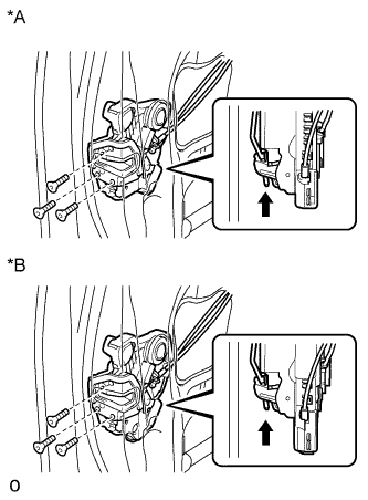
Text in Illustration *A w/o Double Locking System *B w/ Double Locking System 
Slide Insert the front door lock open rod to the front door lock assembly.
-
Check that the front door lock open rod is securely connected to the front door lock assembly.
-
Using a T30 "TORX" wrench, install the front door lock assembly with the 3 screws.
- Torque:
- 5.0 N*m { 51 kgf*cm, 44 in.*lbf }
-
Connect the connector.
-
-
INSTALL FRONT DOOR OUTSIDE HANDLE COVER WITH LOCK CYLINDER ASSEMBLY
-
Install the front door outside handle cover with lock cylinder assembly.
Tech Tips
Make sure that the front door lock cylinder rod is inserted into the front door lock assembly.
-
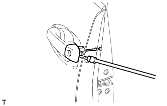
Using a T30 "TORX" socket wrench, install the front door lock cylinder with the screw.
- Torque:
- 4.0 N*m { 41 kgf*cm, 35 in.*lbf }
-
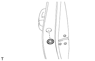
Install the hole plug.
-
-
INSTALL FRONT DOOR REAR LOWER FRAME SUB-ASSEMBLY LH
-
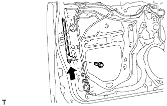
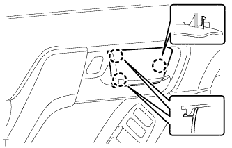
Install the front door rear lower frame sub-assembly with the bolt as shown in the illustration.
-
-
INSTALL FRONT DOOR GLASS RUN LH
-
Install the front door glass run.
-
-
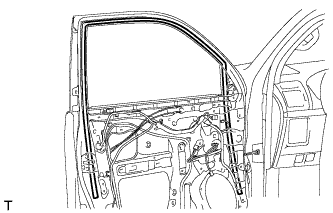
INSTALL FRONT DOOR GLASS SUB-ASSEMBLY LH
-
Connect the cable to the negative (-) battery terminal.
-
Connect the power window regulator master switch assembly and move the front door glass sub-assembly so that the door glass bolt installation locations can be seen.
-
Disconnect the cable from the negative (-) battery terminal and power window regulator master switch assembly.
CAUTION:
Wait at least 90 seconds after disconnecting the cable from the negative (-) battery terminal to disable the SRS system Click here.
-
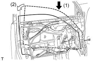
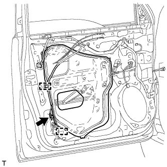
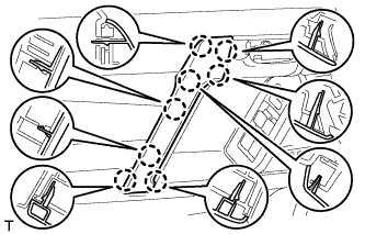
Insert the front door glass sub-assembly into the front door panel along the front door glass run as indicated by the arrows in the order shown in the illustration.
-
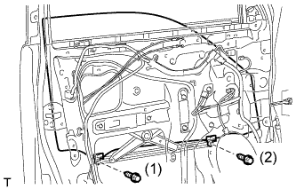
Install the front door glass sub-assembly with the 2 bolts.
- Torque:
- 5.5 N*m { 56 kgf*cm, 49 in.*lbf }
Tech Tips
Tighten the bolts in the order shown in the illustration.
-
-
INSTALL FRONT DOOR SERVICE HOLE COVER LH
-
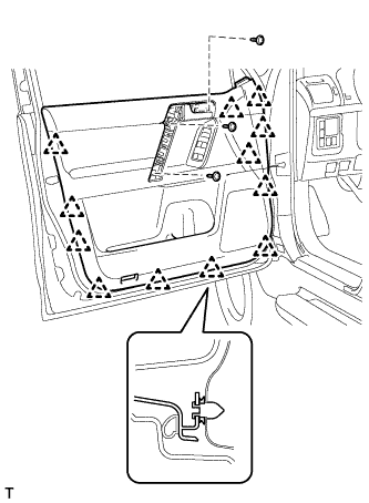
Apply new butyl tape to the front door panel.
-
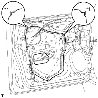
Text in Illustration *1 Reference Point Pass the front door lock remote control cable assembly and front door inside locking cable assembly through a new front door service hole cover.
-
Attach the front door service hole cover using the reference points on the front door panel.
Note
-
There should be no wrinkles or folds after attaching the service hole cover.
-
After attaching the service hole cover, check the seal quality.
Note
Securely install the front door service hole cover preventing wrinkles and air bubbles.
-
-
Attach the 2 clamps.
-
Install the bolt to the front door wire.
-
-
INSTALL FRONT DOOR INNER GLASS WEATHERSTRIP LH
-
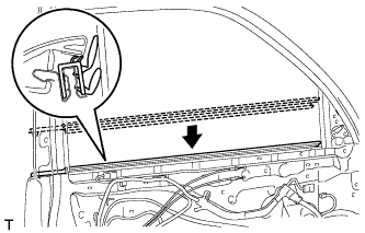
Install the front door inner glass weatherstrip.
-
-
INSTALL FRONT DOOR TRIM BOARD SUB-ASSEMBLY LH
-
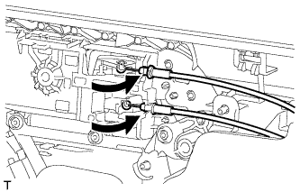
Connect the front door lock remote control cable assembly and front door inside locking cable assembly.
-
Connect 2 connectors.
-
w/ Seat Position Memory System:
-
Connect the connectors.
-
-
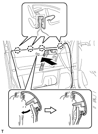
Attach the front door trim board sub-assembly by attaching the 4 claws of the front door inner glass weatherstrip as shown in the illustration.
-
Attach the 12 clips and front door trim board retainer to install the front door trim board sub-assembly.
-
Install the 3 screws.
-
-
INSTALL ASSIST GRIP COVER LH
-
Attach the 8 claws to install the assist grip cover.
-
-
INSTALL NO. 2 DOOR INSIDE HANDLE BEZEL LH
-
Attach the 3 claws to install the inside handle bezel.
-
-
INSTALL FRONT DOOR LOWER FRAME BRACKET GARNISH LH
-
Attach the 2 claws to install the front door lower frame bracket garnish.
-
-
CONNECT CABLE TO NEGATIVE BATTERY TERMINAL
Note
When disconnecting the cable, some systems need to be initialized after the cable is reconnected Click here.
-
CHECK SRS WARNING LIGHT
-
Check the SRS warning light Click here.
-