Click here
-
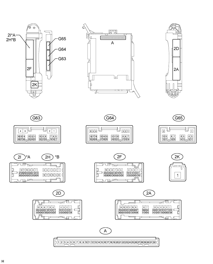
CHECK DRIVER SIDE JUNCTION BLOCK ASSEMBLY, MAIN BODY ECU (MULTIPLEX NETWORK BODY ECU)
Table 1. Text in Illustration *A for LHD *B for RHD
-
Remove the main body ECU (Click here).
-
Measure the voltage and resistance according to the value(s) in the table below.
Terminal No. (Symbol) Wiring Color Terminal Description Condition Specified Condition A-30 (BECU) - Body ground - Auxiliary battery power supply Always 11 to 14 V A-31 (ALTB) - Body ground - Auxiliary battery power supply Always 11 to 14 V A-32 (IG) - Body ground - Ignition switch power supply Ignition switch ON 11 to 14 V A-32 (IG) - Body ground - Ignition switch power supply Ignition switch off Below 1 V A-29 (ACC) - Body ground - ACC power supply Ignition switch ACC 11 to 14 V A-29 (ACC) - Body ground - ACC power supply Ignition switch off Below 1 V A-11 (GND1) - Body ground - Ground Always Below 1 Ω G63-3 (GND2) - Body ground W-B - Body ground Ground Always Below 1 Ω If the result is not as specified, there may be a malfunction in the wire harness.
-
Install the main body ECU (Click here).
-
Measure the voltage according to the value(s) in the table below.
Terminal No. (Symbol) Wiring Color Terminal Description Condition Specified Condition 2I-27 (FLCY) - Body ground*1 R - Body ground Front door LH courtesy switch input Front door LH open Below 1 V 2I-27 (FLCY) - Body ground*1 R - Body ground Front door LH courtesy switch input Front door LH closed 11 to 14 V 2D-31 (FLCY) - Body ground*2 R - Body ground Front door LH courtesy switch input Front door LH open Below 1 V 2D-31 (FLCY) - Body ground*2 R - Body ground Front door LH courtesy switch input Front door LH closed 11 to 14 V 2D-15 (FRCY) - Body ground*1 B - Body ground Front door RH courtesy switch input Front door RH open Below 1 V 2D-15 (FRCY) - Body ground*1 B - Body ground Front door RH courtesy switch input Front door RH closed 11 to 14 V 2H-26 (FRCY) - Body ground*2 B - Body ground Front door RH courtesy switch input Front door RH open Below 1 V 2H-26 (FRCY) - Body ground*2 B - Body ground Front door RH courtesy switch input Front door RH closed 11 to 14 V G65-3 (LCTY) - Body ground*3 V - Body ground Rear door LH courtesy light switch input Rear door LH open Below 1 V G65-3 (LCTY) - Body ground*3 V - Body ground Rear door LH courtesy light switch input Rear door LH closed 11 to 14 V G64-6 (RCTY) - Body ground*3 R - Body ground Rear door RH courtesy light switch input Rear door RH open Below 1 V G64-6 (RCTY) - Body ground*3 R - Body ground Rear door RH courtesy light switch input Rear door RH closed 11 to 14 V G64-19 (BCTY) - Body ground G - Body ground Back door courtesy light switch input Back door open Below 1 V G64-19 (BCTY) - Body ground G - Body ground Back door courtesy light switch input Ignition switch off, all doors closed and back door closed Pulse generation (see waveform 1 or 2) G64-1 (GCTY) - Body ground*4 V - Body ground Glass hatch courtesy switch input Glass hatch open Below 1 V G64-1 (GCTY) - Body ground*4 V - Body ground Glass hatch courtesy switch input Ignition switch off, all doors closed and glass hatch closed Pulse generation (see waveform 3 or 4) G64-7 (LSFL) - Body ground G - Body ground Front door LH lock position switch input Front door LH unlocked Below 1 V G64-7 (LSFL) - Body ground G - Body ground Front door LH lock position switch input Ignition switch off, all doors closed and front door LH locked Pulse generation (see waveform 5 or 6) G64-18 (LSFR) - Body ground G - Body ground Front door RH lock position switch input Front door RH unlocked Below 1 V G64-18 (LSFR) - Body ground G - Body ground Front door RH lock position switch input Ignition switch off, all doors closed and front door RH locked Pulse generation (see waveform 7 or 8) 2I-25 (LSWL) - Body ground*1, *3 B - Body ground Rear door LH lock position switch input Rear door LH unlocked Below 1 V 2I-25 (LSWL) - Body ground*1, *3 B - Body ground Rear door LH lock position switch input Ignition switch off, all doors closed and rear door LH locked Pulse generation (see waveform 9 or 10) 2D-16 (LSWL) - Body ground*2, *3 B - Body ground Rear door LH lock position switch input Rear door LH unlocked Below 1 V 2D-16 (LSWL) - Body ground*2, *3 B - Body ground Rear door LH lock position switch input Ignition switch off, all doors closed and rear door LH locked Pulse generation (see waveform 11 or 12) G63-2 (LSWR) - Body ground*3 V - Body ground Rear door RH lock position switch input Rear door RH unlocked Below 1 V G63-2 (LSWR) - Body ground*3 V - Body ground Rear door RH lock position switch input Ignition switch off, all doors closed and rear door RH locked Pulse generation (see waveform 13 or 14) G65-13 (LSWB) - Body ground SB - Body ground Back door lock position switch input Back door lock unlocked Below 1 V G65-13 (LSWB) - Body ground SB - Body ground Back door lock position switch input Ignition switch off, all doors closed and back door locked Pulse generation (see waveform 15 or 16) G64-25 (PRG) - Body ground LG - Body ground Door control receiver output Key in ignition key cylinder → No key in ignition key cylinder Pulse generation G64-26 (RDA) - Body ground P - Body ground Door control receiver input No key in ignition key cylinder, all doors closed and transmitter switch off → on Pulse generation 2F-13 (BZR) - Body ground GR - Body ground Wireless door lock buzzer signal Wireless door lock buzzer off Below 1 V 2F-13 (BZR) - Body ground GR - Body ground Wireless door lock buzzer signal Wireless door lock buzzer on Pulse generation G64-3 (HAZ) - Body ground W - Body ground Hazard warning signal light signal output Hazard warning signal switch off Below 1 V G64-3 (HAZ) - Body ground W - Body ground Hazard warning signal light signal output Hazard warning signal switch on 11 to 14 V G64-17 (KSW) - Body ground G - Body ground Unlock warning switch input No key in ignition key cylinder Pulse generation (see waveform 17 or 18) G64-17 (KSW) - Body ground G - Body ground Unlock warning switch input Key in ignition key cylinder Below 1 V
-
*1: for LHD
-
*2: for RHD
-
*3: for 5 Door
-
*4: w/ Glass Hatch Opener System
If the result is not as specified, the main body ECU or driver side junction block assembly may have a malfunction.
-
-
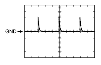
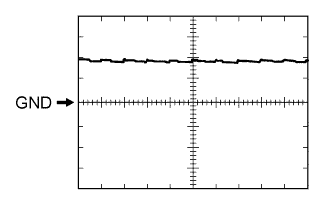
Using an oscilloscope, check waveform 1.
Table 2. Waveform 1 (Reference) Item Content Terminal No. (Symbol) G64-19 (BCTY) - Body ground Tool Setting 5 V/DIV., 20 ms/DIV. Condition Ignition switch off, all doors closed and back door closed -
Using an oscilloscope, check waveform 2.
Table 3. Waveform 2 (Reference) Item Content Terminal No. (Symbol) G64-19 (BCTY) - Body ground Tool Setting 5 V/DIV., 20 ms/DIV. Condition Ignition switch off, all doors closed and back door closed -
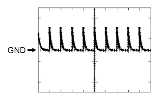
Using an oscilloscope, check waveform 3.
Table 4. Waveform 3 (Reference) Item Content Terminal No. (Symbol) G64-1 (GCTY) - Body ground Tool Setting 5 V/DIV., 20 ms/DIV. Condition Ignition switch off, all doors closed and glass hatch closed -
Using an oscilloscope, check waveform 4.
Table 5. Waveform 4 (Reference) Item Content Terminal No. (Symbol) G64-1 (GCTY) - Body ground Tool Setting 5 V/DIV., 20 ms/DIV. Condition Ignition switch off, all doors closed and glass hatch closed -
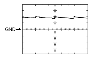
Using an oscilloscope, check waveform 5.
Table 6. Waveform 5 (Reference) Item Content Terminal No. (Symbol) G64-7 (LSFL) - Body ground Tool Setting 5 V/DIV., 20 ms/DIV. Condition Ignition switch off, all doors closed and front door LH locked -
Using an oscilloscope, check waveform 6.
Table 7. Waveform 6 (Reference) Item Content Terminal No. (Symbol) G64-7 (LSFL) - Body ground Tool Setting 5 V/DIV., 20 ms/DIV. Condition Ignition switch off, all doors closed and front door LH locked -
Using an oscilloscope, check waveform 7.
Table 8. Waveform 7 (Reference) Item Content Terminal No. (Symbol) G64-18 (LSFR) - Body ground Tool Setting 5 V/DIV., 20 ms/DIV. Condition Ignition switch off, all doors closed and front door RH locked -
Using an oscilloscope, check waveform 8.
Table 9. Waveform 8 (Reference) Item Content Terminal No. (Symbol) G64-18 (LSFR) - Body ground Tool Setting 5 V/DIV., 20 ms/DIV. Condition Ignition switch off, all doors closed and front door RH locked -
Using an oscilloscope, check waveform 9.
Table 10. Waveform 9 (Reference) Item Content Terminal No. (Symbol) 2I-25 (LSWL) - Body ground Tool Setting 5 V/DIV., 20 ms/DIV. Condition Ignition switch off, all doors closed and rear door LH locked -
Using an oscilloscope, check waveform 10.
Table 11. Waveform 10 (Reference) Item Content Terminal No. (Symbol) 2I-25 (LSWL) - Body ground Tool Setting 5 V/DIV., 20 ms/DIV. Condition Ignition switch off, all doors closed and rear door LH locked -
Using an oscilloscope, check waveform 11.
Table 12. Waveform 11 (Reference) Item Content Terminal No. (Symbol) 2D-16 (LSWL) - Body ground Tool Setting 5 V/DIV., 20 ms/DIV. Condition Ignition switch off, all doors closed and rear door LH locked -
Using an oscilloscope, check waveform 12.
Table 13. Waveform 12 (Reference) Item Content Terminal No. (Symbol) 2D-16 (LSWL) - Body ground Tool Setting 5 V/DIV., 20 ms/DIV. Condition Ignition switch off, all doors closed and rear door LH locked -
Using an oscilloscope, check waveform 13.
Table 14. Waveform 13 (Reference) Item Content Terminal No. (Symbol) G63-2 (LSWR) - Body ground Tool Setting 5 V/DIV., 20 ms/DIV. Condition Ignition switch off, all doors closed and rear door RH locked -
Using an oscilloscope, check waveform 14.
Table 15. Waveform 14 (Reference) Item Content Terminal No. (Symbol) G63-2 (LSWR) - Body ground Tool Setting 5 V/DIV., 20 ms/DIV. Condition Ignition switch off, all doors closed and rear door RH locked -
Using an oscilloscope, check waveform 15.
Table 16. Waveform 15 (Reference) Item Content Terminal No. (Symbol) G65-13 (LSWB) - Body ground Tool Setting 5 V/DIV., 20 ms/DIV. Condition Ignition switch off, all doors closed and back door locked -
Using an oscilloscope, check waveform 16.
Table 17. Waveform 16 (Reference) Item Content Terminal No. (Symbol) G65-13 (LSWB) - Body ground Tool Setting 5 V/DIV., 20 ms/DIV. Condition Ignition switch off, all doors closed and back door locked -
Using an oscilloscope, check waveform 17.
Table 18. Waveform 17 (Reference) Item Content Terminal No. (Symbol) G64-17 (KSW) - Body ground Tool Setting 5 V/DIV., 20 ms/DIV. Condition No key in ignition key cylinder -
Using an oscilloscope, check waveform 18.
Table 19. Waveform 18 (Reference) Item Content Terminal No. (Symbol) G64-17 (KSW) - Body ground Tool Setting 5 V/DIV., 20 ms/DIV. Condition No key in ignition key cylinder
-