POWER DOOR LOCK CONTROL SYSTEM, Diagnostic DTC:B1243

| DTC Code | DTC Name |
|---|---|
| B1243 | GSW Terminal Circuit Malfunction |
DESCRIPTION
If the collision door lock release function does not operate normally, or an open or short in the GSW input circuit of the main body ECU (driver side junction block assembly) is detected, DTC B1243 is stored.
Tech Tips
If DTC B1243 is stored, the speed-sensitive automatic door lock function, shift-linked automatic door lock function and collision door lock release function are prohibited.
| DTC Code | DTC Detection Condition | Trouble Area |
|---|---|---|
| B1243 | Either condition is met:
|
|
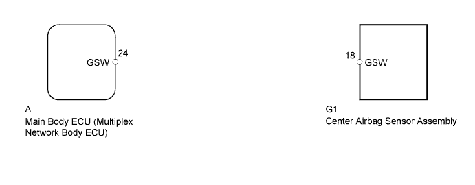
WIRING DIAGRAM
INSPECTION PROCEDURE
Note
-
w/ Navigation system:
After the ignition switch is turned off, the HDD navigation system requires approximately a minute to record various types of memory and settings. As a result, after turning the ignition switch off, wait a minute or more before disconnecting the cable from the negative (-) battery terminal.
-
When disconnecting the cable from the negative (-) battery terminal while performing repairs, some systems need to be initialized after the cable is reconnected Click here.
PROCEDURE
-
CHECK FOR DTC
-
Clear the DTCs Click here.
-
Check for DTCs Click here.
Result Result Proceed to DTC B1243 is output A DTC B1243 is not output B
B 
USE SIMULATION METHOD TO CHECK Click here
A 
-
-
CHECK HARNESS AND CONNECTOR (MAIN BODY ECU - CENTER AIRBAG SENSOR)
-
Disconnect the cable from the negative (-) battery terminal.
-
Remove the main body ECU Click here.
-
Disconnect the G1 center airbag sensor connector.
-
Measure the resistance according to the value(s) in the table below.
Standard Resistance Tester Connection Condition Specified Condition G1-18 (GSW) - A-24 (GSW) Always Below 1 Ω G1-18 (GSW) - Body ground Always 10 kΩ or higher
NG
REPAIR OR REPLACE HARNESS OR CONNECTOR
OK
-
-
CHECK MAIN BODY ECU (GSW VOLTAGE)
-
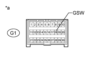
Text in Illustration *a Front view of wire harness connector
(to Center Airbag Sensor)
Disconnect the cable from the negative (-) battery terminal.
-
Disconnect the G1 center airbag sensor connector.
-
Connect the cable to the negative (-) battery terminal.
-
Measure the voltage according to the value(s) in the table below.
Standard Voltage Tester Connection Switch Condition Specified Condition G1-18 (GSW) - Body ground Ignition switch ON 4.5 to 5.5 V
NG
REPLACE MAIN BODY ECU (MULTIPLEX NETWORK BODY ECU) Click here
OK 
REPLACE CENTER AIRBAG SENSOR ASSEMBLY Click here
-