CAN COMMUNICATION SYSTEM (for LHD without Entry and Start System) SYSTEM DIAGRAM

-
SYSTEM DIAGRAM (except 5L-E)
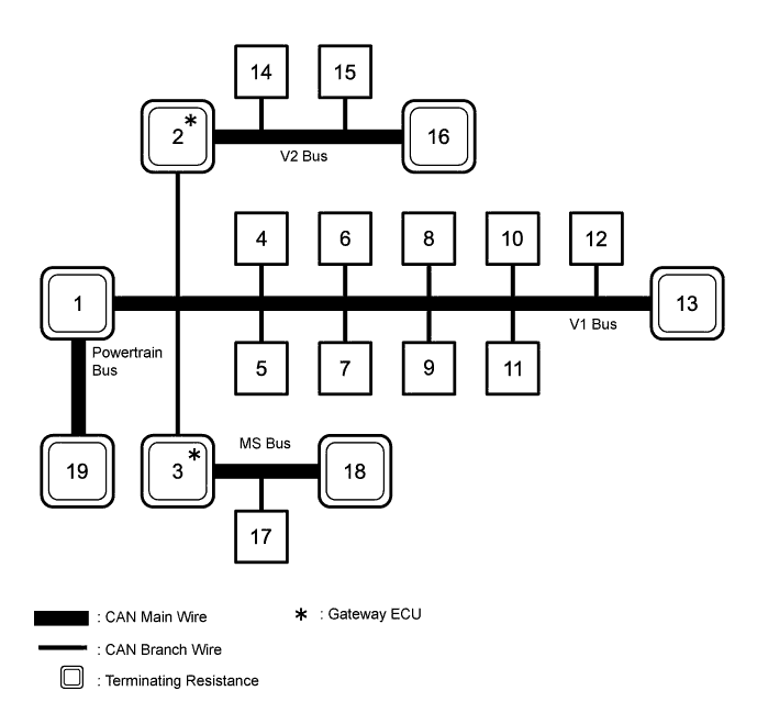
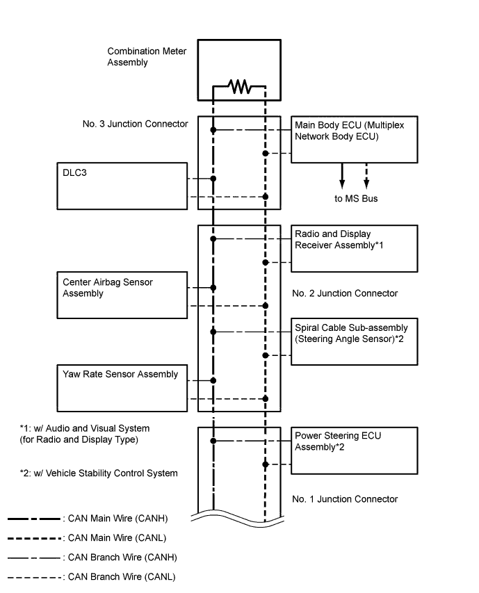
No. ECU/Sensor Name 1 ECM 2 Network gateway ECU*1 3 Main body ECU (multiplex network body ECU) 4 DLC3 5 Yaw rate sensor assembly 6 Center airbag sensor assembly 7 Radio and display receiver assembly*2 8 Spiral cable sub-assembly (steering angle sensor)*3 9 Power steering ECU assembly*3 10 Four wheel drive control ECU 11
-
Master cylinder solenoid (skid control ECU)*4
-
Brake actuator assembly (skid control ECU)*5
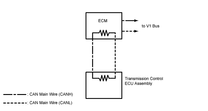
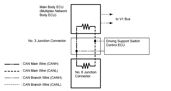
12 Air conditioning amplifier assembly 13 Combination meter assembly 14 Clearance warning ECU assembly*6 15 Headlight swivel ECU assembly*7 16 No. 7 junction connector*1 17 Driving support switch control ECU*8 18 No. 8 junction connector*8 19 Transmission control ECU assembly*9
-
*1: w/ Network Gateway ECU
-
*2: w/ Audio and Visual System (for Radio and Display Type)
-
*3: w/ Vehicle Stability Control System
-
*4: for 1GR-FE, 1KD-FTV
-
*5: for 2TR-FE
-
*6: w/ TOYOTA Parking Assist-sensor System (for 4 Sensor Type)
-
*7: for LED Headlight
-
*8: w/ Multi-function Switch
-
*9: for 1KD-FTV and Automatic Transmission
-
-
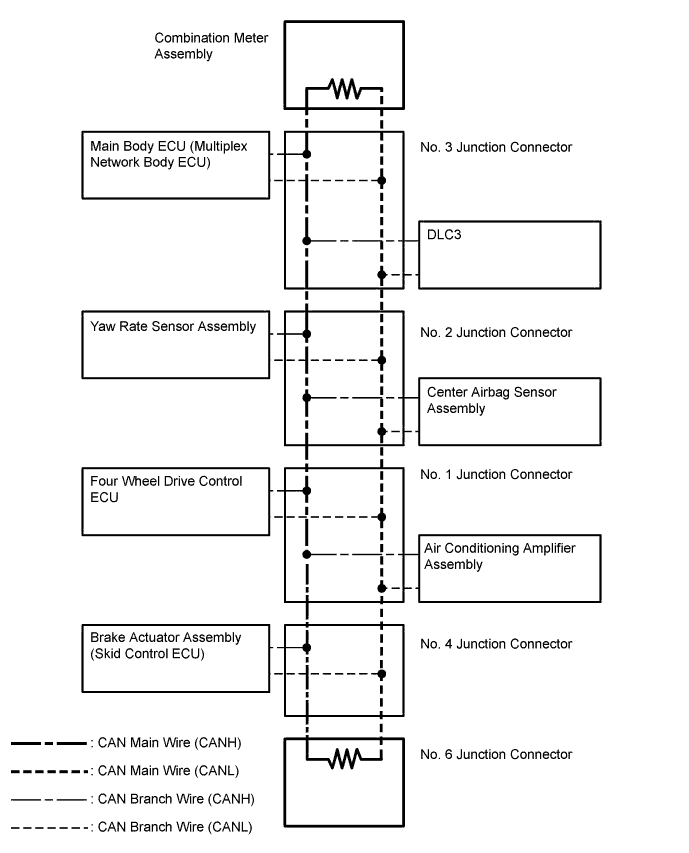
SYSTEM DIAGRAM (for 5L-E)
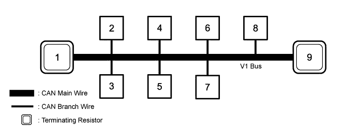
No. ECU/Sensor Name 1 Combination meter assembly 2 Main body ECU (multiplex network body ECU) 3 DLC3 4 Yaw rate sensor assembly 5 Center airbag sensor assembly 6 Air conditioning amplifier assembly 7 Four wheel drive control ECU 8 Brake actuator assembly (skid control ECU) 9 No. 6 junction connector -
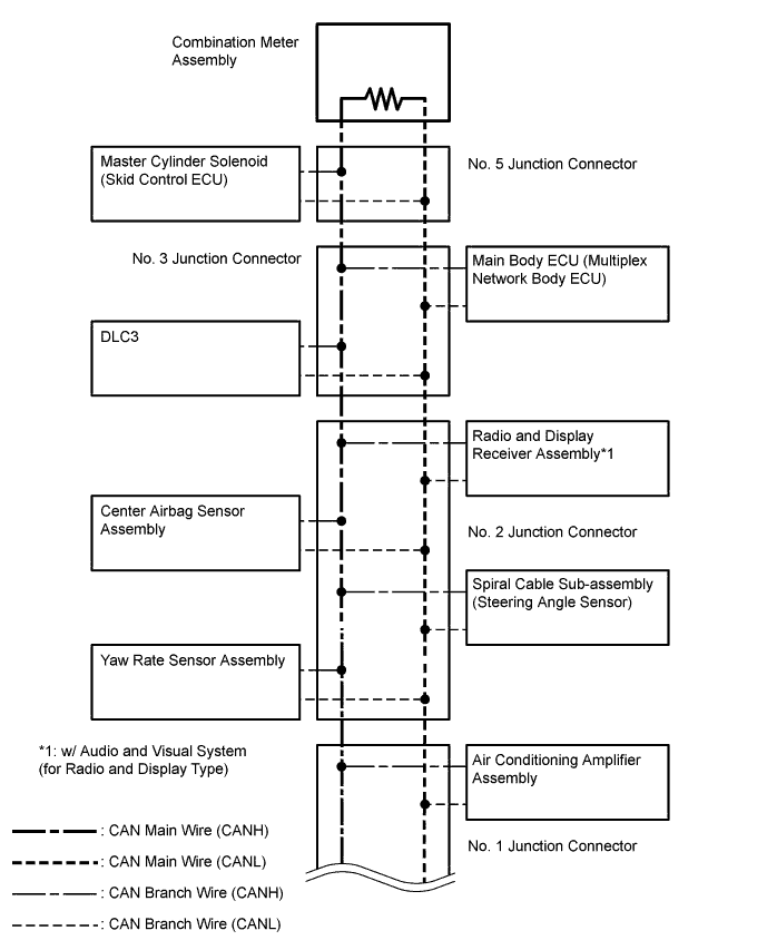
V1 BUS (for 1GR-FE, 1KD-FTV)
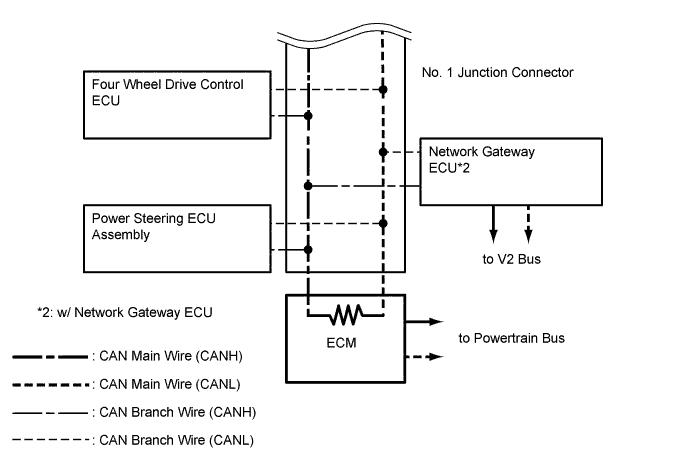
-
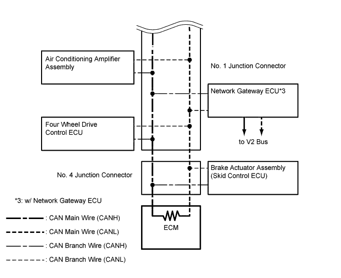
V1 BUS (for 2TR-FE)
-
V1 BUS (for 5L-E)
-
V2 BUS (w/ Network Gateway ECU)
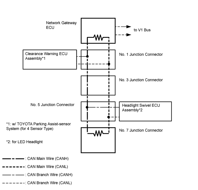
-
MS BUS (w/ Multi-function Switch)
-
POWERTRAIN BUS (for 1KD-FTV and Automatic Transmission)