CAN COMMUNICATION SYSTEM (for LHD with Entry and Start System) Open in CAN Main Wire
DESCRIPTION
There may be an open circuit in the CAN main wire and/or DLC3 CAN branch wire when the resistance between terminals 6 (CANH) and 14 (CANL) of the DLC3 is 70 Ω or higher.
| Symptom | Trouble Area |
|---|---|
| The resistance between terminals 6 (CANH) and 14 (CANL) of the DLC3 is 70 Ω or higher. |
|
-
*1: for 2TR-FE, 5L-E
-
*23: for 1GR-FE, 1KD-FTV
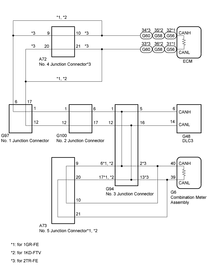
WIRING DIAGRAM
INSPECTION PROCEDURE
Tech Tips
Operating the engine switch, any switches or any doors triggers related ECU and sensor communication with the CAN, which causes resistance variation.
PROCEDURE
-
DISCONNECT CABLE FROM NEGATIVE BATTERY TERMINAL
-
Disconnect the cable from the negative (-) battery terminal before measuring the resistances of the CAN main wire and the CAN branch wire.
CAUTION:
Wait at least 90 seconds after disconnecting the cable from the negative (-) battery terminal to disable the airbag system.
Note
-
After turning the engine switch off, waiting time may be required before disconnecting the cable from the battery terminal. Therefore, make sure to read the disconnecting the cable from the battery terminal notice before proceeding with work Click here.
-
When disconnecting the cable, some systems need to be initialized after the cable is reconnected Click here.
-
NEXT 
-
-
CHECK FOR OPEN IN CAN BUS WIRE (NO. 3 JUNCTION CONNECTOR - DLC3)
-
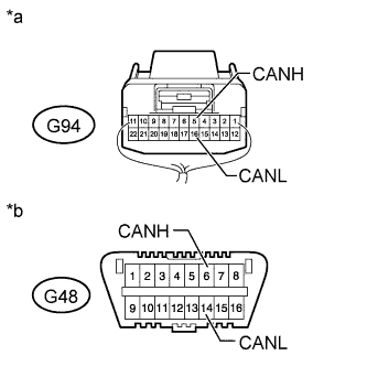
Text in Illustration *a Rear view of wire harness connector
(to No. 3 Junction Connector)
*b Front view of DLC3 Disconnect the G94 No. 3 junction connector.
-
Measure the resistance according to the value(s) in the table below.
Standard Resistance Tester Connection Switch Condition Specified Condition G94-5 (CANH) - G48-6 (CANH) Engine switch off Below 1 Ω G94-16 (CANL) - G48-14 (CANL) Engine switch off Below 1 Ω
NG 
REPAIR OR REPLACE CAN BRANCH WIRE CONNECTED TO DLC3 (CANH, CANL)
OK
-
-
CHECK FOR OPEN IN CAN BUS WIRE (NO. 3 JUNCTION CONNECTOR - ECM OR NO. 6 JUNCTION CONNECTOR)
-
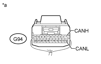
Text in Illustration *a Rear view of wire harness connector
(to No. 3 Junction Connector)
Measure the resistance according to the value(s) in the table below.
Standard Resistance Tester Connection Switch Condition Specified Condition G94-1 (CANH) - G94-12 (CANL) Engine switch off 108 to 132 Ω
NG 
CONNECT CONNECTOR Click here
OK
-
-
CHECK FOR OPEN IN CAN BUS WIRE (NO. 3 JUNCTION CONNECTOR - COMBINATION METER ASSEMBLY)
-
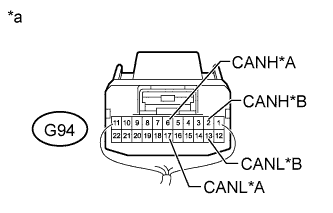
Text in Illustration *A for 1GR-FE, 1KD-FTV *B for 2TR-FE *a Rear view of wire harness connector
(to No. 3 Junction Connector)
Measure the resistance according to the value(s) in the table below.
Standard Resistance for 1GR-FE, 1KD-FTV Tester Connection Switch Condition Specified Condition G94-6 (CANH) - G94-17 (CANL) Engine switch off 108 to 132 Ω for 2TR-FE Tester Connection Switch Condition Specified Condition G94-2 (CANH) - G94-13 (CANL) Engine switch off 108 to 132 Ω Result Result Proceed to OK A NG (for 1GR-FE, 1KD-FTV) B NG (for 2TR-FE) C
B
CONNECT CONNECTOR Click here
C
CONNECT CONNECTOR Click here
A 
REPLACE NO. 3 JUNCTION CONNECTOR
-
-
CONNECT CONNECTOR
-
Reconnect the G94 No. 3 junction connector.
NEXT
-
-
CHECK FOR OPEN IN CAN BUS WIRE (NO. 2 JUNCTION CONNECTOR - ECM)
-
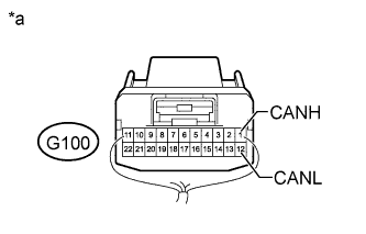
Text in Illustration *a Rear view of wire harness connector
(to No. 2 Junction Connector)
Disconnect the G100 No. 2 junction connector.
-
Measure the resistance according to the value(s) in the table below.
Standard Resistance Tester Connection Switch Condition Specified Condition G100-1 (CANH) - G100-12 (CANL) Engine switch off 108 to 132 Ω
NG
CONNECT CONNECTOR Click here
OK
-
-
CHECK FOR OPEN IN CAN BUS WIRE (NO. 2 JUNCTION CONNECTOR - NO. 3 JUNCTION CONNECTOR)
-
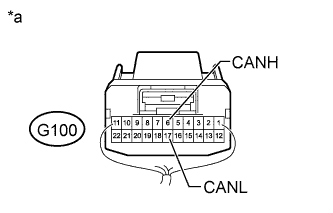
Text in Illustration *a Rear view of wire harness connector
(to No. 2 Junction Connector)
Measure the resistance according to the value(s) in the table below.
Standard Resistance Tester Connection Switch Condition Specified Condition G100-6 (CANH) - G100-17 (CANL) Engine switch off 108 to 132 Ω
NG
REPAIR OR REPLACE CAN MAIN WIRE OR CONNECTOR (NO. 2 JUNCTION CONNECTOR - NO. 3 JUNCTION CONNECTOR)
OK
REPLACE NO. 2 JUNCTION CONNECTOR
-
-
CONNECT CONNECTOR
-
Reconnect the G100 No. 2 junction connector.
NEXT
-
-
CHECK FOR OPEN IN CAN BUS WIRE (NO. 1 JUNCTION CONNECTOR - ECM)
-
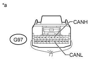
Text in Illustration *a Rear view of wire harness connector
(to No. 1 Junction Connector)
Disconnect the G97 No. 1 junction connector.
-
Measure the resistance according to the value(s) in the table below.
Standard Resistance Tester Connection Switch Condition Specified Condition G97-6 (CANH) - G97-17 (CANL) Engine switch off 108 to 132 Ω Result Result Proceed to OK A NG (for 2TR-FE) B NG (for 1GR-FE) C NG (for 1KD-FTV) D
B
CONNECT CONNECTOR Click here
C
CONNECT CONNECTOR Click here
D
CONNECT CONNECTOR Click here
A
-
-
CHECK FOR OPEN IN CAN BUS WIRE (NO. 1 JUNCTION CONNECTOR - NO. 2 JUNCTION CONNECTOR)
-
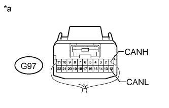
Text in Illustration *a Rear view of wire harness connector
(to No. 1 Junction Connector)
Measure the resistance according to the value(s) in the table below.
Standard Resistance Tester Connection Switch Condition Specified Condition G97-1 (CANH) - G97-12 (CANL) Engine switch off 108 to 132 Ω
NG
REPAIR OR REPLACE CAN MAIN WIRE OR CONNECTOR (NO. 1 JUNCTION CONNECTOR - NO. 2 JUNCTION CONNECTOR)
OK
REPLACE NO. 1 JUNCTION CONNECTOR
-
-
CONNECT CONNECTOR
-
Reconnect the G97 No. 1 junction connector.
NEXT
-
-
CHECK FOR OPEN IN CAN BUS WIRE (NO. 4 JUNCTION CONNECTOR - ECM)
-

Text in Illustration *a Rear view of wire harness connector
(to No. 4 Junction Connector)
Disconnect the A72 No. 4 junction connector.
-
Measure the resistance according to the value(s) in the table below.
Standard Resistance Tester Connection Switch Condition Specified Condition A72-10 (CANH) - A72-21 (CANL) Engine switch off 108 to 132 Ω
NG
CONNECT CONNECTOR Click here
OK
-
-
CHECK FOR OPEN IN CAN BUS WIRE (NO. 4 JUNCTION CONNECTOR - NO. 1 JUNCTION CONNECTOR)
-
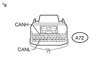
Text in Illustration *a Rear view of wire harness connector
(to No. 4 Junction Connector)
Measure the resistance according to the value(s) in the table below.
Standard Resistance Tester Connection Switch Condition Specified Condition A72-9 (CANH) - A72-20 (CANL) Engine switch off 108 to 132 Ω
NG
REPAIR OR REPLACE CAN MAIN WIRE OR CONNECTOR (NO. 4 JUNCTION CONNECTOR - NO. 1 JUNCTION CONNECTOR)
OK
REPLACE NO. 4 JUNCTION CONNECTOR
-
-
CONNECT CONNECTOR
-
Reconnect the G97 No. 1 junction connector.
NEXT
-
-
CHECK FOR OPEN IN CAN BUS WIRE (ECM - NO. 1 JUNCTION CONNECTOR)
-
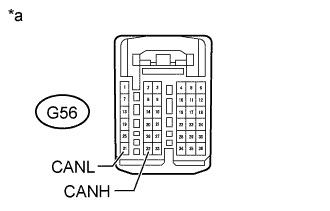
Text in Illustration *a Front view of wire harness connector
(to ECM)
Disconnect the G56 ECM connector.
-
Measure the resistance according to the value(s) in the table below.
Standard Resistance Tester Connection Switch Condition Specified Condition G56-32 (CANH) - G56-31 (CANL) Engine switch off 108 to 132 Ω
NG
REPAIR OR REPLACE CAN MAIN WIRE CONNECTED TO ECM (ECM - NO. 1 JUNCTION CONNECTOR)
OK
REPLACE ECM Click here
-
-
CONNECT CONNECTOR
-
Reconnect the G97 No. 1 junction connector.
NEXT
-
-
CHECK FOR OPEN IN CAN BUS WIRE (ECM - NO. 1 JUNCTION CONNECTOR)
-
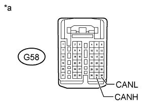
Text in Illustration *a Front view of wire harness connector
(to ECM)
Disconnect the G58 ECM connector.
-
Measure the resistance according to the value(s) in the table below.
Standard Resistance Tester Connection Switch Condition Specified Condition G58-35 (CANH) - G58-36 (CANL) Engine switch off 108 to 132 Ω
NG
REPAIR OR REPLACE CAN MAIN WIRE CONNECTED TO ECM (ECM - NO. 1 JUNCTION CONNECTOR)
OK
REPLACE ECM Click here
-
-
CONNECT CONNECTOR
-
Reconnect the A74 No. 4 junction connector.
NEXT
-
-
CHECK FOR OPEN IN CAN BUS WIRE (ECM - NO. 4 JUNCTION CONNECTOR)
-
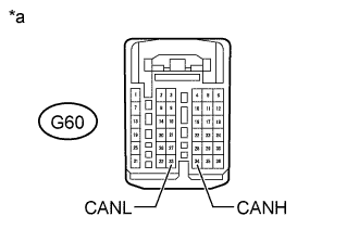
Text in Illustration *a Front view of wire harness connector
(to ECM)
Disconnect the G60 ECM connector.
-
Measure the resistance according to the value(s) in the table below.
Standard Resistance Tester Connection Switch Condition Specified Condition G60-34 (CANH) - G60-33 (CANL) Engine switch off 108 to 132 Ω
NG
REPAIR OR REPLACE CAN MAIN WIRE CONNECTED TO ECM (ECM - NO. 4 JUNCTION CONNECTOR)
OK
REPLACE ECM Click here
-
-
CONNECT CONNECTOR
-
Reconnect the G94 No. 3 junction connector.
NEXT
-
-
CHECK FOR OPEN IN CAN BUS WIRE (NO. 5 JUNCTION CONNECTOR - COMBINATION METER ASSEMBLY)
-
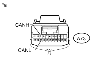
Text in Illustration *a Rear view of wire harness connector
(to No. 5 Junction Connector)
Disconnect the A73 No. 5 junction connector.
-
Measure the resistance according to the value(s) in the table below.
Standard Resistance Tester Connection Switch Condition Specified Condition A73-9 (CANH) - A73-20 (CANL) Engine switch off 108 to 132 Ω
NG
CONNECT CONNECTOR Click here
OK
-
-
CHECK FOR OPEN IN CAN BUS WIRE (NO. 5 JUNCTION CONNECTOR - NO. 3 JUNCTION CONNECTOR)
-
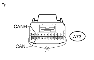
Text in Illustration *a Rear view of wire harness connector
(to No. 5 Junction Connector)
Measure the resistance according to the value(s) in the table below.
Standard Resistance Tester Connection Switch Condition Specified Condition A73-10 (CANH) - A73-21 (CANL) Engine switch off 108 to 132 Ω
NG
REPAIR OR REPLACE CAN MAIN WIRE OR CONNECTOR (NO. 5 JUNCTION CONNECTOR - NO. 3 JUNCTION CONNECTOR)
OK
REPLACE NO. 5 JUNCTION CONNECTOR
-
-
CONNECT CONNECTOR
-
Reconnect the A73 No. 5 junction connector.
NEXT
-
-
CHECK FOR OPEN IN CAN BUS WIRE (COMBINATION METER ASSEMBLY - NO. 5 JUNCTION CONNECTOR)
-
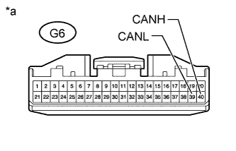
Text in Illustration *a Front view of wire harness connector
(to Combination Meter Assembly)
Disconnect the G6 combination meter assembly connector.
-
Measure the resistance according to the value(s) in the table below.
Standard Resistance Tester Connection Switch Condition Specified Condition G6-40 (CANH) - G6-39 (CANL) Engine switch off 108 to 132 Ω
NG
REPAIR OR REPLACE CAN MAIN WIRE CONNECTED TO COMBINATION METER ASSEMBLY (COMBINATION METER ASSEMBLY - NO. 5 JUNCTION CONNECTOR)
OK
REPLACE COMBINATION METER ASSEMBLY Click here
-
-
CONNECT CONNECTOR
-
Reconnect the G94 No. 3 junction connector.
NEXT
-
-
CHECK FOR OPEN IN CAN BUS WIRE (COMBINATION METER ASSEMBLY - NO. 3 JUNCTION CONNECTOR)
-
Text in Illustration *a Front view of wire harness connector
(to Combination Meter Assembly)
Disconnect the G6 combination meter assembly connector.
-
Measure the resistance according to the value(s) in the table below.
Standard Resistance Tester Connection Switch Condition Specified Condition G6-40 (CANH) - G6-39 (CANL) Engine switch off 108 to 132 Ω
NG
REPAIR OR REPLACE CAN MAIN WIRE CONNECTED TO COMBINATION METER ASSEMBLY (COMBINATION METER ASSEMBLY - NO. 3 JUNCTION CONNECTOR)
OK
REPLACE COMBINATION METER ASSEMBLY Click here
-