DESCRIPTION
This DTC is stored when LIN communication between the front power window regulator motor assembly RH*1 or LH*2 and main body ECU (multiplex network body ECU) stops for 10 seconds or more.
-
*1: for LHD
-
*2: for RHD
| DTC Code | DTC Detection Condition | Trouble Area |
|---|---|---|
| B2322 | No communication between the front power window regulator motor assembly RH*1 or LH*2 and main body ECU (multiplex network body ECU) for 10 seconds or more. |
|
-
*1: for LHD
-
*2: for RHD
INSPECTION PROCEDURE
-
When using the intelligent tester with the ignition switch off to troubleshoot:
Connect the intelligent tester to the vehicle and turn a courtesy light switch on and off at 1.5 second intervals until communication between the intelligent tester and vehicle begins.
-
Inspect the fuses and bulbs for circuits related to this system before performing the following inspection procedure.
When communication between the front power window regulator motor assembly RH*1 or LH*2 and main body ECU (multiplex network body ECU) stops, DTC B2325 is also stored.
-
*1: for LHD
-
*2: for RHD
PROCEDURE
- Click here
CLEAR DTC
-
Clear the DTCs (Click here).
- NEXTClick here
-
- Click here
CHECK FOR DTC
-
Check for DTCs (Click here).
OK DTC B2322 is not output.
- OKClick here
- NGClick here
-
- Click here
CHECK HARNESS AND CONNECTOR (MAIN BODY ECU - FRONT POWER WINDOW REGULATOR MOTOR)
-
Remove the main body ECU (multiplex network body ECU) from the driver side junction block assembly (Click here).
-
Disconnect the J7*1 or K7*2 front power window regulator motor assembly connector.
-
*1: for LHD
-
*2: for RHD
-
-
Measure the resistance according to the value(s) in the table below.
Standard Resistance for LHD Tester Connection Condition Specified Condition A-16 (LIN2) - J7-9 (LIN) Always Below 1 Ω A-16 (LIN2) or J7-9 (LIN) - Body ground Always 10 kΩ or higher for RHD Tester Connection Condition Specified Condition A-16 (LIN2) - K7-9 (LIN) Always Below 1 Ω A-16 (LIN2) or K7-9 (LIN) - Body ground Always 10 kΩ or higher
- OKClick here
- NGClick here
-
- Click here
CHECK HARNESS AND CONNECTOR (FRONT POWER WINDOW REGULATOR MOTOR - BATTERY AND BODY GROUND)
-
Disconnect the J7*1 or K7*2 front power window regulator motor assembly connector.
-
*1: for LHD
-
*2: for RHD
-
-
Measure the resistance according to the value(s) in the table below.
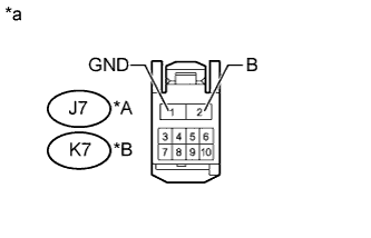
Standard Resistance for LHD Tester Connection Condition Specified Condition J7-1 (GND) - Body ground Always Below 1 Ω for RHD Tester Connection Condition Specified Condition K7-1 (GND) - Body ground Always Below 1 Ω -
Measure the voltage according to the value(s) in the table below.
Standard Voltage for LHD Tester Connection Condition Specified Condition J7-2 (B) - Body ground Always 11 to 14 V for RHD Tester Connection Condition Specified Condition K7-2 (B) - Body ground Always 11 to 14 V Table 1. Text in Illustration *A for LHD *B for RHD *a Front view of wire harness connector
(to Front Power Window Regulator Motor Assembly)
- OKClick here
- NGClick here
-
- Click here
REPLACE FRONT POWER WINDOW REGULATOR MOTOR ASSEMBLY
-
Temporarily replace the front power window regulator motor assembly RH*1 or LH*2 with a new or normally functioning one (Click here).
-
*1: for LHD
-
*2: for RHD
-
- NEXTClick here
-
- Click here
CLEAR DTC
-
Clear the DTCs (Click here).
- NEXTClick here
-
- Click here
CHECK FOR DTC
-
Check for DTCs (Click here).
OK DTC B2322 is not output.
- OKClick here
- NGClick here
-
- Click here
END (FRONT POWER WINDOW REGULATOR MOTOR IS DEFECTIVE)
- Click here
USE SIMULATION METHOD TO CHECKClick here
- Click here
REPAIR OR REPLACE HARNESS OR CONNECTOR
- Click here
REPAIR OR REPLACE HARNESS OR CONNECTOR
- Click here
REPLACE MAIN BODY ECU (MULTIPLEX NETWORK BODY ECU)Click here