LIN COMMUNICATION SYSTEM, Diagnostic DTC:B1273

| DTC Code | DTC Name |
|---|---|
| B1273 | Sliding Roof ECU Communication Stop |
DESCRIPTION
This DTC is stored when LIN communication between the sliding roof drive gear sub-assembly and main body ECU (multiplex network body ECU) stops for 10 seconds or more.
| DTC Code | DTC Detection Condition | Trouble Area |
|---|---|---|
| B1273 | No communication between the sliding roof drive gear sub-assembly and main body ECU (multiplex network body ECU) for 10 seconds or more. |
|
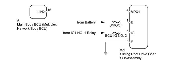
WIRING DIAGRAM
INSPECTION PROCEDURE
Note
-
When using the intelligent tester with the ignition switch off to troubleshoot:
Connect the intelligent tester to the vehicle and turn a courtesy light switch on and off at 1.5 second intervals until communication between the intelligent tester and vehicle begins.
-
Inspect the fuses and bulbs for circuits related to this system before performing the following inspection procedure.
Tech Tips
When communication between the sliding roof drive gear sub-assembly and main body ECU (multiplex network body ECU) stops, DTC B2325 is also stored.
PROCEDURE
-
CLEAR DTC
-
Clear the DTCs Click here.
NEXT 
-
-
CHECK FOR DTC
-
Check for DTCs Click here.
OK DTC B1273 is not output.
NG 
CHECK HARNESS AND CONNECTOR (MAIN BODY ECU - SLIDING ROOF DRIVE GEAR) Click here
OK 
USE SIMULATION METHOD TO CHECK Click here
-
-
CHECK HARNESS AND CONNECTOR (MAIN BODY ECU - SLIDING ROOF DRIVE GEAR)
-
Remove the main body ECU (multiplex network body ECU) from the driver side junction block assembly Click here.
-
Disconnect the W2 sliding roof drive gear sub-assembly connector.
-
Measure the resistance according to the value(s) in the table below.
Standard Resistance Tester Connection Condition Specified Condition A-16 (LIN2) - W2-4 (MPX1) Always Below 1 Ω A-16 (LIN2) or W2-4 (MPX1) - Body ground Always 10 kΩ or higher
NG 
REPAIR OR REPLACE HARNESS OR CONNECTOR
OK
-
-
CHECK HARNESS AND CONNECTOR (SLIDING ROOF DRIVE GEAR - BATTERY AND BODY GROUND)
-
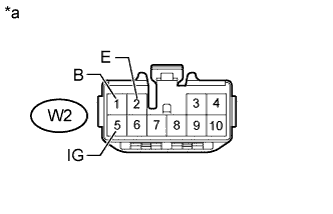
Text in Illustration *a Front view of wire harness connector
(to Sliding Roof Drive Gear Sub-assembly)
Disconnect the W2 sliding roof drive gear sub-assembly connector.
-
Measure the resistance according to the value(s) in the table below.
Standard Resistance Tester Connection Condition Specified Condition W2-2 (E) - Body ground Always Below 1 Ω -
Measure the voltage according to the value(s) in the table below.
Standard Voltage Tester Connection Switch Condition Specified Condition W2-1 (B) - Body ground Always 11 to 14 V W2-5 (IG) - Body ground Ignition switch ON 11 to 14 V
NG
REPAIR OR REPLACE HARNESS OR CONNECTOR
OK
-
-
REPLACE SLIDING ROOF DRIVE GEAR SUB-ASSEMBLY
-
Temporarily replace the sliding roof drive gear sub-assembly with a new or normally functioning one Click here.
NEXT
-
-
CLEAR DTC
-
Clear the DTCs Click here.
NEXT
-
-
CHECK FOR DTC
-
Check for DTCs Click here.
OK DTC B1273 is not output.
NG
REPLACE MAIN BODY ECU Click here
OK
END (SLIDING ROOF DRIVE GEAR IS DEFECTIVE)
-