STEREO JACK ADAPTER ASSEMBLY REMOVAL

-
PRECAUTION
Note
After turning the ignition switch off, waiting time may be required before disconnecting the cable from the battery terminal. Therefore, make sure to read the disconnecting the cable from the battery terminal notice before proceeding with work Click here.
-
DISCONNECT CABLE FROM NEGATIVE BATTERY TERMINAL
Note
When disconnecting the cable, some systems need to be initialized after the cable is reconnected Click here.
-
REMOVE INTEGRATION CONTROL AND PANEL ASSEMBLY
-
Detach the 4 clips.
-
Disconnect the connector and remove the integration control and panel assembly.
-
-
REMOVE NO. 2 INSTRUMENT PANEL FINISH PANEL CUSHION
-
Detach the 5 clips and remove the No. 2 instrument panel finish panel cushion.
-
-
REMOVE NO. 1 INSTRUMENT PANEL FINISH PANEL CUSHION
Tech Tips
Use the same procedure described for the No. 2 instrument panel finish panel cushion.
-
REMOVE INSTRUMENT PANEL FINISH PANEL END LH
-
Detach the 4 clips and remove the instrument panel finish panel end LH.
-
-
REMOVE INSTRUMENT PANEL FINISH PANEL END RH
-
Detach the 4 clips and remove the instrument panel finish panel end RH.
-
-
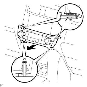
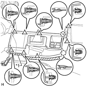
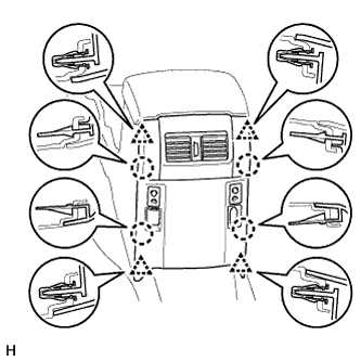
REMOVE FRONT CONSOLE UPPER PANEL GARNISH
-
w/o Seat Heater System:
-
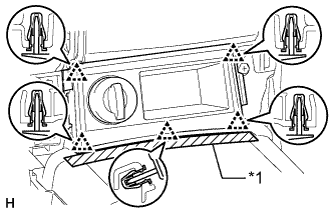
Text in Illustration *1 Protective Tape Put protective tape around the front console upper panel garnish.
-
Detach the 5 clips and remove the front console upper panel garnish.
-
Disconnect the connector.
-
-
w/o CRAWL:
-
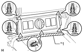
Text in Illustration *1 Protective Tape Put protective tape around the front console upper panel garnish.
-
Detach the 5 clips and remove the front console upper panel garnish.
-
Disconnect each connector.
-
-
w/ CRAWL:
-
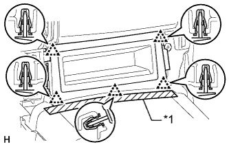
Text in Illustration *1 Protective Tape Put protective tape around the front console upper panel garnish.
-
Detach the 5 clips and remove the front console upper panel garnish.
-
-
-
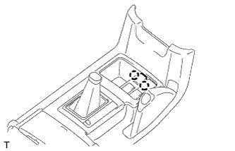
REMOVE SHIFT LEVER KNOB SUB-ASSEMBLY
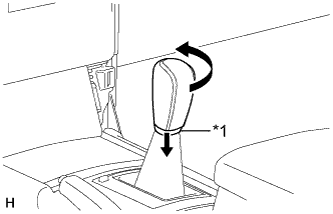
Text in Illustration *1 Shifting Hole Cover
-
Move the shifting hole cover downward.
-
Twist the shift lever knob in the direction indicated by the arrow and remove it.
-
-
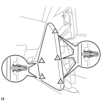
REMOVE CONSOLE PANEL SUB-ASSEMBLY (for Automatic Transmission)
Text in Illustration *1 Protective Tape
-
Put protective tape around the console panel.
-
Using a moulding remover, detach the 8 clips and 2 claws.
-
Disconnect each connector and remove the console panel.
-
-
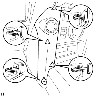
REMOVE CONSOLE PANEL SUB-ASSEMBLY (for Manual Transmission)
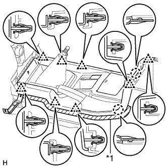
Text in Illustration *1 Protective Tape
-
Put protective tape around the console panel.
-
Using a moulding remover, detach the 8 clips and 2 claws.
-
Disconnect each connector and remove the console panel.
-
-
REMOVE NO. 1 STEREO JACK ADAPTER ASSEMBLY (for Automatic Transmission)
-
Detach the 2 claws and remove the stereo jack adapter.
-
-
REMOVE NO. 1 STEREO JACK ADAPTER ASSEMBLY (for Manual Transmission)
-
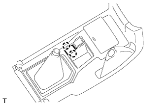
Detach the 2 claws and remove the stereo jack adapter.
-
-
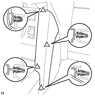
REMOVE REAR CONSOLE END PANEL SUB-ASSEMBLY
-
Detach the 4 clips and 4 claws.
-
Disconnect each connector and remove the rear console end panel.
-
-
REMOVE VIDEO (VIDEO ADAPTER) TERMINAL
-
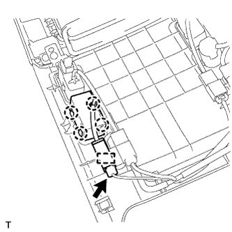
Disconnect the connector.
-
Detach the clamp and 4 claws and remove the video terminal.
-
-
REMOVE HEADPHONE TERMINAL
-
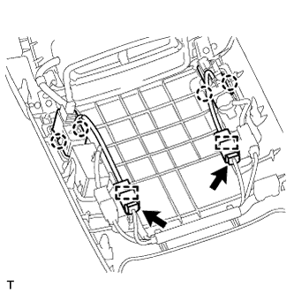
Disconnect the 2 connectors.
-
Detach the 4 claws and 2 clamps and remove the 2 headphone terminals.
-