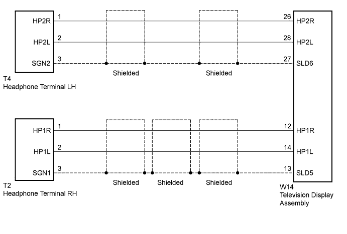
REAR SEAT ENTERTAINMENT SYSTEM Sound Signal Circuit between Headphone Terminal and Television Display
DESCRIPTION
This circuit sends a sound signal from the television display to the headphone terminal.
WIRING DIAGRAM
INSPECTION PROCEDURE
PROCEDURE
-
CHECK HEADPHONES
-
Check the malfunctioning headphones.
Result Result Proceed to Malfunction in headphone terminal LH side A Malfunction in headphone terminal RH side B
B 
CHECK HARNESS AND CONNECTOR (TELEVISION DISPLAY ASSEMBLY - HEADPHONE TERMINAL RH) Click here
A 
-
-
CHECK HARNESS AND CONNECTOR (TELEVISION DISPLAY ASSEMBLY - HEADPHONE TERMINAL LH)
-
Disconnect the W14 television display assembly connector.
-
Disconnect the T4 headphone terminal LH connector.
-
Measure the resistance according to the value(s) in the table below.
Standard Resistance Tester Connection Condition Specified Condition W14-26 (HP2R) - T4-1 (HP2R) Always Below 1 Ω W14-27 (SLD6) - T4-3 (SGN2) Always Below 1 Ω W14-28 (HP2L) - T4-2 (HP2L) Always Below 1 Ω W14-26 (HP2R) - Body ground Always 10 kΩ or higher W14-27 (SLD6) - Body ground Always 10 kΩ or higher W14-28 (HP2L) - Body ground Always 10 kΩ or higher
NG 
REPAIR OR REPLACE HARNESS OR CONNECTOR
OK
-
-
CHECK TELEVISION DISPLAY ASSEMBLY
-
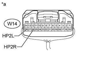
Text in Illustration *a Component with harness connected
(Television Display Assembly)
Remove the television display assembly connector still connected Click here.
-
Using an oscilloscope, check the waveform between each terminal and the body ground according to the conditions as shown in the table below.
Standard Tester Connection Condition Specified Condition W14-26 (HP2R) - Body ground Audio sound being produced A waveform synchronized with sound is output W14-28 (HP2L) - Body ground
NG
REPLACE TELEVISION DISPLAY ASSEMBLY Click here
OK 
PROCEED TO NEXT SUSPECTED AREA SHOWN IN PROBLEM SYMPTOMS TABLE Click here
-
-
CHECK HARNESS AND CONNECTOR (TELEVISION DISPLAY ASSEMBLY - HEADPHONE TERMINAL RH)
-
Disconnect the W14 television display assembly connector.
-
Disconnect the T2 headphone terminal RH connector.
-
Measure the resistance according to the value(s) in the table below.
Standard Resistance Tester Connection Condition Specified Condition W14-12 (HP1R) - T2-1 (HP1R) Always Below 1 Ω W14-13 (SLD5) - T2-3 (SGN1) Always Below 1 Ω W14-14 (HP1L) - T2-2 (HP1L) Always Below 1 Ω W14-12 (HP1R) - Body ground Always 10 kΩ or higher W14-13 (SLD5) - Body ground Always 10 kΩ or higher W14-14 (HP1L) - Body ground Always 10 kΩ or higher
NG
REPAIR OR REPLACE HARNESS OR CONNECTOR
OK
-
-
CHECK TELEVISION DISPLAY ASSEMBLY
-
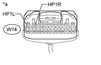
Text in Illustration *a Component with harness connected
(Television Display Assembly)
Remove the television display assembly connector still connected Click here.
-
Using an oscilloscope, check the waveform between each terminal and the body ground according to the conditions as shown in the table below.
Standard Tester Connection Condition Specified Condition W14-12 (HP1R) - Body ground Audio sound being produced A waveform synchronized with sound is output W14-14 (HP1L) - Body ground
NG
REPLACE TELEVISION DISPLAY ASSEMBLY Click here
OK
PROCEED TO NEXT SUSPECTED AREA SHOWN IN PROBLEM SYMPTOMS TABLE Click here
-