STEERING COLUMN ASSEMBLY (for Manual Tilt and Manual Telescopic Steering Column) INSTALLATION

-
CONNECT NO. 2 STEERING INTERMEDIATE SHAFT SUB-ASSEMBLY
-
Align the matchmarks on the No. 2 steering intermediate shaft and power steering gear.
-
Install the bolt.
- Torque:
- 36 N*m { 367 kgf*cm, 27 ft.*lbf }
-
-
INSTALL NO. 1 STEERING COLUMN HOLE COVER SUB-ASSEMBLY
-
Install the hole cover with the 4 bolts.
- Torque:
- 5.0 N*m { 51 kgf*cm, 44 in.*lbf }
Note
Do not fold back the boot part of the steering hole cover or extend it excessively. If it is extended excessively, return it to its original position.
-
-
CONNECT STEERING INTERMEDIATE SHAFT ASSEMBLY
-
Align the matchmarks on the No. 2 steering intermediate shaft assembly and steering intermediate shaft assembly.
Tech Tips
Install the steering intermediate shaft to the inside of the vehicle.
-
Install the bolt.
- Torque:
- 36 N*m { 367 kgf*cm, 27 ft.*lbf }
-
-
INSTALL NO. 1 FRONT FENDER APRON TO FRAME SEAL LH
-
w/ KDSS:
Install the apron seal with the 7 clips.
-
w/o KDSS:
Install the apron seal with the 4 clips.
-
-
INSTALL STEERING COLUMN ASSEMBLY
-
Align the matchmarks on the steering intermediate shaft and steering column.
-
Install the steering column with the 4 nuts.
- Torque:
- 15 N*m { 153 kgf*cm, 11 ft.*lbf }
-
Install the bolt.
- Torque:
- 36 N*m { 367 kgf*cm, 27 ft.*lbf }
-
Attach the claws to connect the wire harness protector and wire harness.
-
-
INSTALL INSTRUMENT LOWER PANEL FINISH PANEL SUB-ASSEMBLY (w/o Knee Airbag)
-
INSTALL NO. 1 INSTRUMENT LOWER PANEL AIRBAG ASSEMBLY (w/ Knee Airbag)
-
INSTALL TRANSPONDER KEY AMPLIFIER (Transponder Key)
-
INSTALL COMBINATION SWITCH ASSEMBLY WITH SPIRAL CABLE SUB-ASSEMBLY
-
Using pliers, grip the claws of the clamp and install the combination switch assembly with spiral cable sub-assembly to the steering column assembly with the clamp.
-
Connect the connectors to the combination switch with spiral cable.
-
-
INSTALL STEERING COLUMN UPPER COVER
-
Attach the claw to install the steering column upper cover.
-
Attach the 4 clips to install the steering column upper cover to the instrument cluster finish panel.
-
-
INSTALL STEERING COLUMN LOWER COVER
-
Attach the 2 claws to install the steering column lower cover.
-
Install the 2 screws.
-
-
ADJUST SPIRAL CABLE SUB-ASSEMBLY
-
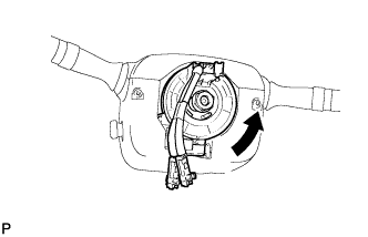
Rotate the spiral cable sub-assembly with steering sensor counterclockwise slowly by hand until it feels firm.
CAUTION:
Do not turn the spiral cable sub-assembly with steering sensor by the airbag wire harness.
-
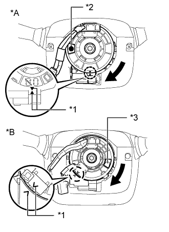
Text in Illustration *A w/o Steering Heater *B w/ Steering Heater *1 Alignment Mark *2 Colored Part *3 Flat Cable Rotate the spiral cable sub-assembly with steering sensor clockwise approximately 2.5 turns to align the marks so that the colored part or the flat cable shown in the illustration is visible.
CAUTION:
Do not turn the spiral cable sub-assembly with steering sensor by the airbag wire harness.
Tech Tips
The spiral cable sub-assembly with steering sensor can be rotated approximately 2.5 turns to both the left and right from the center position.
-
-
INSTALL STEERING WHEEL ASSEMBLY
-
CHECK FRONT WHEELS FACING STRAIGHT AHEAD
-
INSTALL FRONT WHEEL LH
-
CONNECT CABLE TO NEGATIVE BATTERY TERMINAL
Note
When disconnecting the cable, some systems need to be initialized after the cable is reconnected Click here.
-
CHECK SRS WARNING LIGHT