STEERING SYSTEM ADJUSTMENT

-
STEERING OFF CENTER ADJUSTMENT PROCEDURE
Tech Tips
This is the adjustment procedure for when the steering is off center.
-
Check if the steering wheel is off center.
-
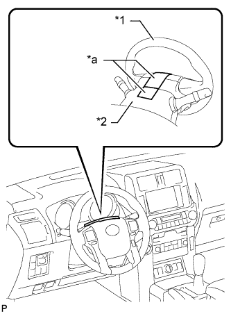
Text in Illustration *1 Steering Wheel *2 Steering Column Upper Cover *a Masking Tape Apply masking tape to the top center of the steering wheel and steering column upper cover.
-
Drive the vehicle in a straight line for 100 m (328 ft.) at a constant speed of 56 km/h (35 mph) and hold the steering wheel to maintain course.
-
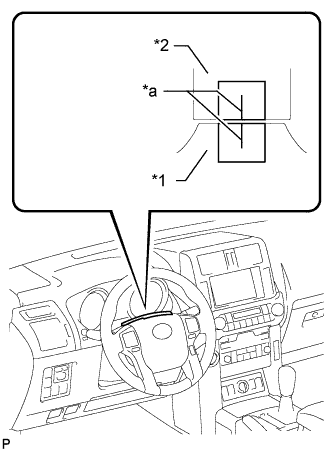
Text in Illustration *1 Steering Wheel *2 Steering Column Upper Cover *a Marked Line Draw a line on the masking tape as shown in the illustration.
-
Turn the steering wheel to the center position.
Tech Tips
Look at the upper surface of the steering wheel, steering spoke and SRS airbag line to find the center position.
-
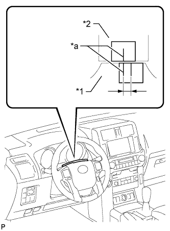
Text in Illustration *1 Steering Wheel *2 Steering Column Upper Cover *a Marked Line Draw a new line on the masking tape on the steering wheel as shown in the illustration.
-
Measure the distance between the 2 lines on the masking tape on the steering wheel.
-
Convert the measured distance to a steering angle value.
Tech Tips
-
Measured distance 1 mm (0.0394 in.) = Steering angle of approximately 1°.
-
Make a note of the steering angle.
-
-
-
Adjust the steering angle.
-
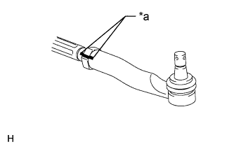
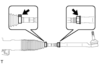
Text in Illustration *a Matchmark Place matchmarks RH and LH tie rod ends and rack ends respectively where it can be easily seen.
-
Using a paper gauge, measure the distance from the RH and LH tie rod ends to the rack end screws.
Tech Tips
-
Measure both the RH and LH sides.
-
Make a note of the measured values.
-
-
Remove the RH and LH boot clips from the rack boots.
-
Loosen the RH and LH lock nuts.
-
Turn the RH and LH rack ends by the same amount (but in different directions) according to the steering angle value
Tech Tips
One 360° turn of a rack end (1.5 mm (0.0591 in.) horizontal movement) is equal to a 12° change in steering angle.
-
Tighten the RH and LH lock nuts to the specified torque.
- Torque:
- 88 N*m { 897 kgf*cm, 65 ft.*lbf }
Note
Make sure that the difference in length between the RH and LH tie rod ends and rack end screws is within 1.5 mm (0.0591 in.).
-
Install the RH and LH boot clips.
-
-