HEATED STEERING WHEEL SYSTEM Steering Wheel does not Heat Up When Heated Steering Wheel Switch is Pressed
DESCRIPTION
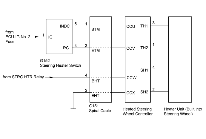
WIRING DIAGRAM
INSPECTION PROCEDURE
PROCEDURE
-
CHECK STEERING HEATER SWITCH (LED OPERATION)
-
Check the illumination condition of the LED.
Result LED Condition Proceed to Illuminates Engine switch on (IG)
Heated steering wheel switch is pushed
B Does not illuminate Engine switch on (IG)
Heated steering wheel switch is pushed and held continuously for 10 seconds or more
A
B 
INSPECT STEERING WHEEL ASSEMBLY (HEATER·THERMOSTAT) Click here
A 
-
-
INSPECT STEERING WHEEL ASSEMBLY (THERMISTOR)
-
Disconnect the steering wheel controller connector.
-
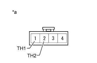
Text in Illustration *a Front view of wire harness connector
(to Heated Steering Wheel Controller)
Measure the resistance according to the value(s) in the table below.
Standard Resistance Tester Connection Condition Specified Condition 1 (TH2) - 2 (TH1) 10 to 30 °C(50 to 86°F) 8.132 to 18.43 kΩ
NG 
REPLACE STEERING WHEEL ASSEMBLY Click here
OK
-
-
INSPECT STEERING WHEEL ASSEMBLY (HEATER·THERMOSTAT)
-
Disconnect the steering wheel controller connector.
-
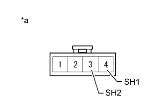
Text in Illustration *a Front view of wire harness connector
(to Heated Steering Wheel Controller)
Measure the resistance according to the value(s) in the table below.
Standard Resistance Tester Connection Condition Specified Condition 4 (SH1) - 3 (SH2) 20°C (68°F) 1.89 to 2.25 Ω
NG
REPLACE STEERING WHEEL ASSEMBLY Click here
OK
-
-
CHECK HARNESS AND CONNECTOR (STEERING HEATER SWITCH - SPIRAL CABLE)
-
Disconnect the G152 steering heater switch connector.
-
Disconnect the G151 spiral cable connector.
-
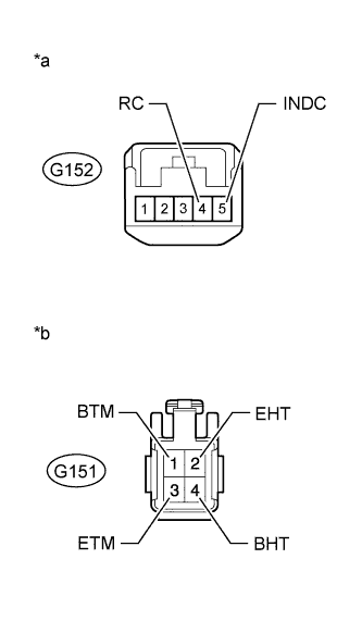
Text in Illustration *a Front view of wire harness connector
(to Steering Heater Switch)
*b Front view of wire harness connector
(to Spiral Cable)
Measure the resistance according to the value(s) in the table below.
Standard Resistance Tester Connection Condition Specified Condition G152-5 (INDC) - G151-1 (BTM) Always Below 1 Ω G152-4 (RC) - G151-3 (ETM) Always Below 1 Ω G151-2 (EHT) - Body ground Always Below 1 Ω -
Measure the voltage according to the value(s) in the table below.
Standard Voltage Tester Connection Switch Condition Specified Condition G151-4 (BHT) - Body ground Engine switch on (IG) 11 to 14 V
NG
REPAIR OR REPLACE WIRE HARNESS OR CONNECTOR
OK
-
-
INSPECT SPIRAL CABLE SUB-ASSEMBLY
Note
If there are any defects as mentioned below, replace the spiral cable with a new one:
Scratches, cracks, dents or chips in the connector or spiral cable.
-
Disconnect the G151 spiral cable connector.
-
Disconnect the heated steering wheel controller connector.
-
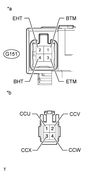
Text in Illustration *a Component without harness connected
(Spiral Cable)
*b Front view of harness connector
(to Heated Steering Wheel Controller)
Measure the resistance according to the value(s) in the table below.
Standard Resistance Tester Connection Condition Specified Condition 1 (CCU) - G151-1 (BTM) Always Below 1 Ω 2 (CCV) - G151-3 (ETM) Always Below 1 Ω 3 (CCX) - G151-2 (EHT) Always Below 1 Ω 4 (CCW) - G151-4 (BHT) Always Below 1 Ω
NG
REPLACE SPIRAL CABLE SUB-ASSEMBLY Click here
OK
-
-
CHECK STEERING HEATER SWITCH
-
Disconnect the G152 steering heater switch connector.
-
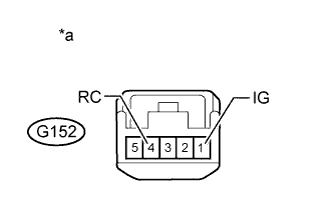
Text in Illustration *a Component without harness connected
(to Steering Heater Switch)
Measure the voltage according to the value(s) in the table below.
Tech Tips
As the circuit has a diode, perform the measurement in diode test mode and make sure that the polarity is correct.
Standard Voltage Tester Connection
Positive (+) tester probe - Negative (-) tester probe
Switch Condition Specified Condition G152-1 (IG) - G152-4 (RC) Heated steering wheel switch is pushed Below 1.25 V
NG
REPLACE STEERING HEATER SWITCH Click here
OK 
REPLACE STEERING WHEEL HEATER CONTROL ASSEMBLY Click here
-