STEERING GEAR REMOVAL

Tech Tips
-
Use the same procedure for RHD and LHD vehicles.
-
The procedure listed below is for LHD vehicles.
-
PLACE FRONT WHEELS FACING STRAIGHT AHEAD
-
REMOVE FRONT WHEELS
-
REMOVE ENGINE ASSEMBLY
-
for 1GR-FE:
Remove the engine Click here.
-
for 1KD-FTV:
Remove the engine Click here.
-
for 5L-E:
Remove the engine Click here.
-
for 2TR-FE:
Remove the engine Click here.
-
-
DISCONNECT NO. 2 STEERING INTERMEDIATE SHAFT
-
for Manual Tilt and Manual Telescopic Steering Column:
Disconnect the No. 2 steering intermediate shaft Click here.
-
for Power Tilt and Power Telescopic Steering Column:
Disconnect the No. 2 steering intermediate shaft Click here.
-
-
DISCONNECT TIE ROD END SUB-ASSEMBLY LH
-
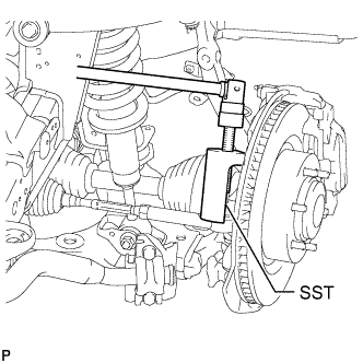
Using SST, disconnect the tie rod end assembly.
- SST
- 09610-20012
-
-
DISCONNECT TIE ROD END SUB-ASSEMBLY RH
Tech Tips
Use the same procedures described for the LH side.
-
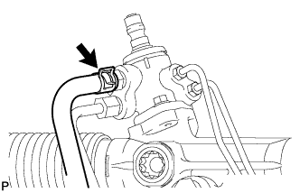
DISCONNECT PRESSURE FEED TUBE ASSEMBLY (for LHD)
-
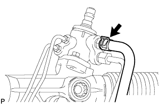
Remove the clamp and disconnect the pressure feed tube (return tube side) from the steering gear.
-
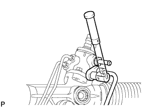
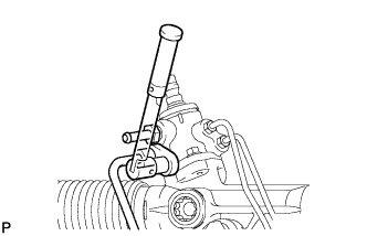
Using a union nut wrench, disconnect the pressure feed tube (pressure feed tube side) from the steering gear.
-
Remove the bolt and disconnect the pressure feed tube clamp.
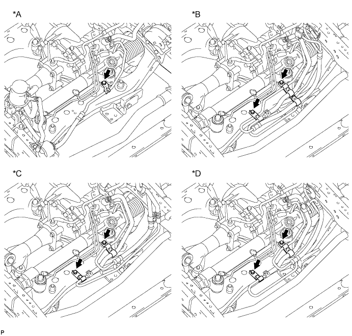
Text in Illustration *A for 1GR-FE: *B for 1KD-FTV: *C for 2TR-FE: *D for 5L-E:
-
-
DISCONNECT PRESSURE FEED TUBE ASSEMBLY (for RHD)
-
Remove the clamp and disconnect the pressure feed tube (return tube side) from the steering gear.
-
Using a union nut wrench, disconnect the pressure feed tube (pressure feed tube side) from the steering gear.
-
Remove the bolt and disconnect the pressure feed tube clamp.
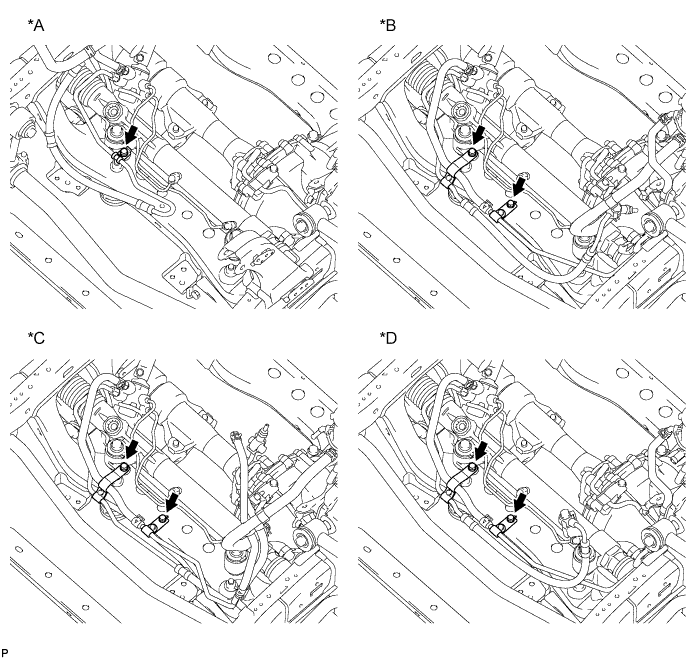
Text in Illustration *A for 1GR-FE: *B for 1KD-FTV: *C for 2TR-FE: *D for 5L-E:
-
-
REMOVE RACK AND PINION POWER STEERING GEAR ASSEMBLY
-
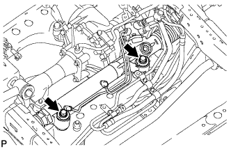
Remove the 2 bolts, 2 nuts and steering gear assembly.
Note
Because the nut has its own stopper, do not turn the nut. Tighten the bolt with the nut fixed in place.
-