- Click here
INSTALL VANE PUMP ASSEMBLY
-
Install the vane pump with the 2 bolts.
43 N*m 438 kgf*cm 32 ft.*lbf -
Install the wire harness bracket with the bolt.
43 N*m 438 kgf*cm 32 ft.*lbf
-
- Click here
CONNECT PRESSURE FEED TUBE
-
Install a new gasket to the pressure feed tube.
-
Connect the pressure feed tube and install the union bolt.
50 N*m 510 kgf*cm 37 ft.*lbf Tip:Make sure the stopper of the pressure feed tube touches the vane pump.
-
- Click here
CONNECT NO. 1 OIL RESERVOIR TO PUMP HOSE
-
Connect the No. 1 oil reservoir to pump hose to the vane pump assembly with the clip.
-
- Click here
CONNECT POWER STEERING OIL PRESSURE SWITCH CONNECTOR
-
Connect the 2 connectors.
-
- Click here
INSTALL FAN AND GENERATOR V BELT
-
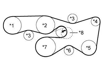
Set the V belt onto every part.
Table 1. Text in Illustration *1 Vane Pump *2 Water Pump *3 No. 2 Idler *4 Generator *5 Cooler Compressor or Idler Pulley *6 No. 1 Idler *7 Crankshaft *8 V-ribbed Belt Tensioner -
While turning the belt tensioner counterclockwise, remove the pin.
Note:Make sure that the V belt is properly installed to each pulley.
-
Check that the belt fits properly in the ribbed grooves.
Tip:Make sure to check by hand that the belt has not slipped out of the grooves on the bottom of the pulley.
-
- Click here
INSTALL AIR CLEANER CASE
- Click here
INSTALL AIR CLEANER FILTER ELEMENT SUB-ASSEMBLY
- Click here
INSTALL AIR CLEANER CAP AND HOSE
-
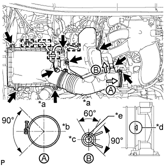
Install the air cleaner cap and hose.
Table 2. Text in Illustration *a Top *b Front *c RH *d Align cutout portion of hose with protrusion of throttle *e Paint Mark
-
Install the air cleaner cap and hose with the bolt and fasten the 4 hook clamps.
5.0 N*m 51 kgf*cm 44 in.*lbf -
Tighten the clamp.
5.0 N*m 51 kgf*cm 44 in.*lbf -
Attach the 4 clamps and connect the ventilation hose, vacuum hose and mass air flow meter connector.
Tip:The direction of the hose clamp is indicated in the illustration.
-
-
- Click here
INSTALL V-BANK COVER SUB-ASSEMBLY
-
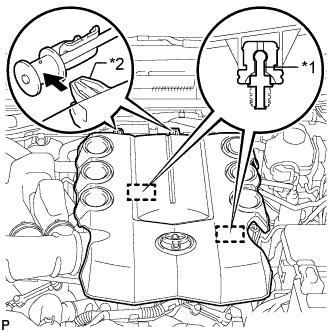
Attach the 2 V-bank cover hooks to the bracket. Then align the 2 V-bank cover grommets with the 2 pins and press down on the V-bank cover to attach the pins.
Table 3. Text in Illustration *1 Pin *2 Hook
-
- Click here
INSTALL FRONT FENDER APRON SEAL RH
-
Install the apron seal with the 5 clips.
-
- Click here
INSTALL FRONT WHEEL RH
for steel wheel 112 N*m 1137 kgf*cm 82 ft.*lbf for aluminum wheel 103 N*m 1050 kgf*cm 76 ft.*lbf - Click here
CONNECT CABLE TO NEGATIVE BATTERY TERMINAL
- Click here
ADD POWER STEERING FLUID
- Click here
BLEED POWER STEERING FLUID
-
Check the fluid level.
-
Jack up the front of the vehicle and support it with stands.
-
Turn the steering wheel.
-
With the engine stopped, turn the wheel slowly from lock to lock several times.
-
-
Lower the vehicle.
-
Start the engine.
-
Run the engine at idle for a few minutes.
-
-
Turn the steering wheel.
-
With the engine idling, turn the wheel to the left or right full lock position and keep it there for 2 to 3 seconds, then turn the wheel to the opposite full lock position and keep it there for 2 to 3 seconds.*1
-
Repeat *1 several times.
-
-
Stop the engine.
-
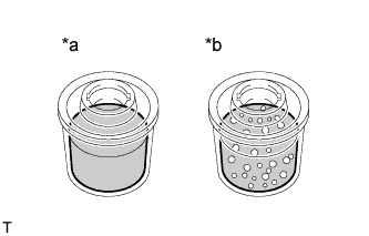
Check for foaming or emulsification.
Table 4. Text in Illustration *a CORRECT *b INCORRECT If the system has to be bled twice specifically because of foaming or emulsification, check for fluid leaks in the power steering system.
-
Check the fluid level.
-
- Click here
INSPECT FOR POWER STEERING FLUID LEAK