HYDRAULIC BRAKE BOOSTER (for RHD) INSTALLATION

-
INSTALL BRAKE BOOSTER GASKET
-
Install a new brake booster gasket to the hydraulic brake booster.
-
-
INSTALL HYDRAULIC BRAKE BOOSTER ASSEMBLY
-
Install the hydraulic brake booster assembly with the 4 nuts.
- Torque:
- 14 N*m { 145 kgf*cm, 10 ft.*lbf }
-
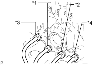
Connect the 4 brake lines to the correct positions of the hydraulic brake booster assembly as shown in the illustration.
Tech Tips
-
*1: To front wheel cylinder RH
-
*2: To front wheel cylinder LH
-
*3: To rear wheel cylinder RH
-
*4: To rear wheel cylinder LH
-
-
Install the clamp with the bolt.
- Torque:
- 8.5 N*m { 87 kgf*cm, 75 in.*lbf }
-
Using a union nut wrench, connect the 4 brake lines to the hydraulic brake booster assembly.
- Torque:
- 15 N*m { 155 kgf*cm, 11 ft.*lbf }
Note
Use the formula to calculate special torque values for situations where a union nut wrench is combined with a torque wrench Click here.
-
Connect the 2 brake tube clamps to the body.
-
Install the brake tube to the clamps.
-
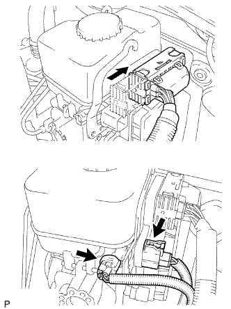
Connect the 3 connectors to the hydraulic brake booster.
-
-
INSTALL PUSH ROD PIN
-
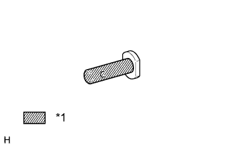
Text in Illustration *1 Lithium soap base glycol grease Apply a light coat of lithium soap base glycol grease to the inner surface of the hole on the brake pedal lever.
-
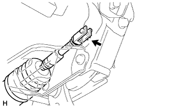
Set the master cylinder push rod clevis in place, insert the push rod pin from the left side of the vehicle, and then install a new clip.
-
-
INSTALL CLUTCH MASTER CYLINDER ASSEMBLY
-
Install the clutch master cylinder assembly Click here.
-
-
CONNECT WATER HOSE JOINT
-
w/ Rear Heater:
Connect the water hose joint.
- Torque:
- 5.4 N*m { 55 kgf*cm, 48 ft.*lbf }
-
-
INSTALL LOWER NO . 1 INSTRUMENT PANEL AIRBAG ASSEMBLY
-
Install the lower No. 1 instrument panel airbag assembly Click here.
-
-
CONNECT CABLE TO NEGATIVE BATTERY TERMINAL
Note
When disconnecting the cable, some systems need to be initialized after the cable is reconnected Click here
-
BLEED BRAKE SYSTEM
CAUTION:
If air is bled without using the intelligent tester, damage or accidents may result. Therefore, always use the intelligent tester when bleeding air.
-
Turn the ignition switch to ON.
-
Remove the brake master cylinder reservoir filler cap assembly.
-
Add brake fluid until the fluid level is between the MIN and MAX lines of the reservoir.
-
Repeatedly depress the brake pedal and bleed air from the bleeder plug of the front disc brake cylinder RH.
-
Repeat the step above until the air is completely bled, and then tighten the bleeder plug while depressing the brake pedal.
- Torque:
- 11 N*m { 110 kgf*cm, 8 ft.*lbf }
-
Bleed the air from the bleeder plug of the front disc brake cylinder LH using the same procedure as for the RH side.
-
With the brake pedal depressed, loosen the bleeder plug of the rear disc brake cylinder RH, continue to hold the brake pedal and allow brake fluid to be drained from the bleeder plug while the pump motor operates.
Tech Tips
-
Air is bled as the pump motor operates while the brake pedal is being depressed.
-
Be sure to release the brake pedal to stop the motor after approximately 100 seconds of continuous operation.
-
As brake fluid is continuously drained while the pump operates, it is not necessary to repeatedly depress the brake pedal.
-
-
When there is no more air in the brake fluid, tighten the bleeder plug, and then release the brake pedal.
- Torque:
- 11 N*m { 110 kgf*cm, 8 ft.*lbf }
-
Bleed the air from the bleeder plug of the rear disc brake cylinder LH using the same procedure as for the RH side.
-
Turn the ignition switch off and connect the intelligent tester to the DLC3.
-
Turn the ignition switch to ON.
-
Turn the intelligent tester on.
-
Enter the following menus: Chassis / ABS/VSC/TRC / Utility / Air Bleeding.
Note
To protect the solenoid from overheating, the solenoid operation stops automatically in 4 seconds, and then the solenoid will not respond to commands for an additional 20 seconds.
-
Repeatedly depress the brake pedal several times, and then, with the brake pedal depressed, turn FR Line on and bleed air.
Tech Tips
Air returns to the brake master cylinder reservoir together with the brake fluid and is bled from the brake system.
Note
-
As it is not possible to visually confirm that air is being bled, repeat this step 10 times.
-
Do not loosen the bleeder plug.
-
-
Turn FL Line on and bleed air using the same procedures as for FR.
-
Turn RR Line on, loosen the bleeder plug of the rear disc brake cylinder RH and drain brake fluid.
Tech Tips
-
Do not depress the brake pedal.
-
As brake fluid is automatically drained while the pump and solenoid operate, it is not necessary to operate the brake pedal.
-
-
Repeat the step above until the air is completely bled, and then tighten the bleeder plug.
- Torque:
- 11 N*m { 110 kgf*cm, 8 ft.*lbf }
-
Turn RL Line on and bleed air from the bleeder plug of the rear disc brake cylinder LH using the same procedure as for the RH side.
-
Turn the intelligent tester off and turn the ignition switch off.
-
Inspect for brake fluid leaks.
-
Check and adjust the brake fluid level Click here.
-
Clear the DTCs Click here.
-
-
FILL RESERVOIR WITH BRAKE FLUID
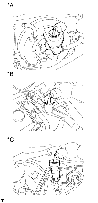
Text in Illustration *A for LHD (2TR-FE, 5L-E) *B for LHD (1GR-FE, 1KD-FTV) *C for RHD
-
Fill the reservoir with brake fluid.
Brake fluid SAE J1703 or FMVSS No. 116 DOT 3
-
-
BLEED CLUTCH LINE
-
Remove the bleeder plug cap of the release cylinder.
-
Connect a vinyl tube to the bleeder plug.
-
Depress the clutch pedal several times, and then loosen the bleeder plug while the pedal is depressed.
-
When fluid no longer comes out, tighten the bleeder plug, and then release the clutch pedal.
-
Repeat the previous 2 steps until all the air in the fluid is completely bled.
-
Tighten the bleeder plug.
- Torque:
- 11 N*m { 110 kgf*cm, 8 ft.*lbf }
-
Install the bleeder plug cap.
-
Check that all the air has been bled from the clutch line.
-
-
CHECK FLUID LEVEL IN RESERVOIR
-
Check the fluid level.
If the brake fluid level is low, check for leaks and inspect the disc brake pad. If necessary, refill the reservoir with brake fluid after repair or replacement.
Brake fluid SAE J1703 or FMVSS No. 116 DOT 3
-
-
CHECK FOR BRAKE FLUID LEAK FROM CLUTCH LINE
-
CHECK AND ADJUST BRAKE PEDAL
-
Check and adjust brake pedal Click here.
-
-
INSPECT BRAKE MASTER CYLINDER OPERATION
-
Inspect the brake master cylinder operation Click here.
-
-
PERFORM YAW RATE AND ACCELERATION SENSOR ZERO POINT CALIBRATION
Note
When replacing the hydraulic brake booster assembly, perform yaw rate and acceleration sensor zero point calibration and acquire information about the following specification as necessary Click here,
-
Downhill assist control calibration
-
Crawl control calibration
-