VEHICLE STABILITY CONTROL SYSTEM (for Vacuum Brake Booster) VSC Buzzer Circuit
DESCRIPTION
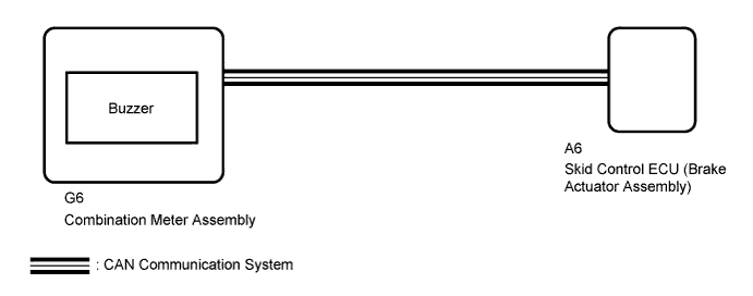
The skid control ECU (brake actuator assembly) is connected to the combination meter assembly via CAN communication.
The combination meter assembly has a built-in buzzer.
WIRING DIAGRAM
INSPECTION PROCEDURE
Note
When replacing the skid control ECU (brake actuator assembly), perform calibration Click here.
PROCEDURE
-
CHECK CAN COMMUNICATION LINE
-
Check if CAN communication system DTCs are output (for LHD without Entry and Start System: Click here, for RHD without Entry and Start System: Click here.
Result Result Proceed to DTC not output A DTC output for LHD without Entry and Start System B DTC output for RHD without Entry and Start System C
B 
GO TO CAN COMMUNICATION SYSTEM (HOW TO PROCEED WITH TROUBLESHOOTING) Click here
C
GO TO CAN COMMUNICATION SYSTEM (HOW TO PROCEED WITH TROUBLESHOOTING) Click here
A 
-
-
READ VALUE USING INTELLIGENT TESTER (BUZZER)
-
Turn the engine switch off.
-
Connect the intelligent tester to the DLC3.
-
Turn the engine switch on (IG).
-
Turn the intelligent tester on.
-
Enter the following menus: Chassis / ABS/VSC/TRAC / Data List.
ABS/VSC/TRAC Tester Display Measurement Item/Range Normal Condition Diagnostic Note Buzzer Buzzer/ ON or OFF ON: Buzzer on
OFF: Buzzer off
The combination meter has a built-in buzzer. -
When performing the Buzzer Active Test, check Buzzer in the Data List Click here.
ABS/VSC/TRAC Tester Display Test Part Control Range Diagnostic Note Buzzer Buzzer Buzzer ON/OFF The buzzer can be heard. Result Result Proceed to Data List Display Data List Display when Performing Active Test ON/OFF Operation ON Changes between ON and OFF A Does not change between ON and OFF B OFF Changes between ON and OFF A Does not change between ON and OFF B
B 
INSPECT COMBINATION METER ASSEMBLY Click here
A 
GO TO METER / GAUGE SYSTEM (HOW TO PROCEED WITH TROUBLESHOOTING) Click here
-
-
INSPECT COMBINATION METER ASSEMBLY
-
Inspect the combination meter Click here.
NG
REPLACE COMBINATION METER ASSEMBLY Click here
OK
REPLACE BRAKE ACTUATOR ASSEMBLY Click here
-