INSPECTION PROCEDURE
When replacing the brake actuator assembly, perform calibration (Click here).
PROCEDURE
- Click here
CHECK CAN COMMUNICATION SYSTEM
-
Check if CAN communication system DTCs are output (for LHD without Entry and Start System:Click here, for RHD without Entry and Start System:Click here).
Table 1. Result Result Proceed to DTC not output A DTC output for LHD without Entry and Start System B DTC output for RHD without Entry and Start System C
-
- Click here
INSPECT VSC OFF SWITCH
-
Remove the VSC OFF switch (Click here).
-
Measure the resistance according to the value(s) in the table below.
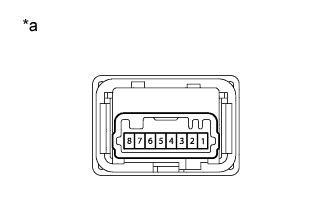
Standard Resistance Tester Connection Switch Condition Specified Condition 6 - 3 Switch is not pushed 10 kΩ or higher Switch is pushed Below 1 Ω Table 2. Text in Illustration *a Component without harness connected
(VSC OFF Switch)
- OKClick here
- NGClick here
-
- Click here
CHECK HARNESS AND CONNECTOR (SKID CONTROL ECU - VSC OFF SWITCH)
-
Disconnect the A6 skid control ECU connector.
-
Disconnect the G9 VSC OFF switch connector.
-
Measure the resistance according to the value(s) in the table below.
Standard Resistance Tester Connection Condition Specified Condition A6-30 (CSW) - G9-6 Always Below 1 Ω A6-30 (CSW) - Body ground Always 10 kΩ or higher G9-3 - Body ground Always Below 1 Ω
- OKClick here
- NGClick here
-
- Click here
READ VALUE USING INTELLIGENT TESTER (TRC/VSC OFF MODE)
-
Turn the ignition switch off.
-
Connect the Intelligent tester to the DLC3.
-
Turn the ignition switch to ON.
-
Turn the intelligent tester on.
-
Enter the following menus: Chassis / ABS/VSC/TRC / Data List.
Table 3. ABS/VSC/TRC Tester Display Measurement Item/Range Normal Condition Diagnostic Note TRC/VSC Off Mode TRC/VSC off mode/ Normal, TRC OFF or VSC OFF Normal: Normal mode
TRC OFF: TRC OFF mode
VSC OFF: VSC OFF mode
- -
Check that the mode display changes according to VSC OFF switch operation.
OK Display changes according to switch operation.
- OKClick here
- NGClick here
-
- Click here
REPLACE BRAKE ACTUATOR ASSEMBLYClick here
- Click here
GO TO CAN COMMUNICATION SYSTEM (HOW TO PROCEED WITH TROUBLESHOOTING)Click here
- Click here
GO TO CAN COMMUNICATION SYSTEM (HOW TO PROCEED WITH TROUBLESHOOTING)Click here
- Click here
GO TO METER / GAUGE SYSTEM (HOW TO PROCEED WITH TROUBLESHOOTING)Click here
- Click here
REPLACE VSC OFF SWITCHClick here
- Click here
REPAIR OR REPLACE HARNESS OR CONNECTOR