VEHICLE STABILITY CONTROL SYSTEM (for Vacuum Brake Booster) VSC OFF Indicator Light Remains ON
DESCRIPTION
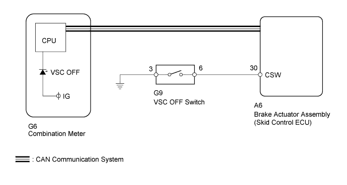
The skid control ECU is connected to the combination meter via CAN communication.
Pressing the VSC OFF switch turns off traction control and pressing and holding this switch turns off traction and VSC controls. If VSC control turns off, the VSC OFF indicator light comes on.
WIRING DIAGRAM
INSPECTION PROCEDURE
Note
-
When replacing the brake actuator assembly, perform calibration Click here.
-
As there may be malfunctions in the transfer system related to when the transfer operates in L4, check the transfer system first Click here.
PROCEDURE
-
CHECK CAN COMMUNICATION SYSTEM
-
Check if CAN communication system DTCs are output (for LHD without Entry and Start System: Click here, for RHD without Entry and Start System: Click here.
Result Result Proceed to DTC not output A DTC output for LHD without Entry and Start System B DTC output for RHD without Entry and Start System C
B 
GO TO CAN COMMUNICATION SYSTEM (HOW TO PROCEED WITH TROUBLESHOOTING) Click here
C
GO TO CAN COMMUNICATION SYSTEM (HOW TO PROCEED WITH TROUBLESHOOTING) Click here
A 
-
-
INSPECT VSC OFF SWITCH
-
Remove the VSC OFF switch Click here.
-
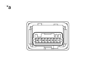
Text in Illustration *a Component without harness connected
(VSC OFF Switch)
Measure the resistance according to the value(s) in the table below.
Standard Resistance Tester Connection Switch Condition Specified Condition 6 - 3 Switch is not pushed 10 kΩ or higher Switch is pushed Below 1 Ω
NG
REPLACE VSC OFF SWITCH Click here
OK
-
-
CHECK HARNESS AND CONNECTOR (SKID CONTROL ECU - VSC OFF SWITCH)
-
Disconnect the A6 skid control ECU connector.
-
Disconnect the G9 VSC OFF switch connector.
-
Measure the resistance according to the value(s) in the table below.
Standard Resistance Tester Connection Condition Specified Condition A6-30 (CSW) - G9-6 Always Below 1 Ω A6-30 (CSW) - Body ground Always 10 kΩ or higher G9-3 - Body ground Always Below 1 Ω
NG
REPAIR OR REPLACE HARNESS OR CONNECTOR
OK
-
-
READ VALUE USING INTELLIGENT TESTER (TRC/VSC OFF MODE)
-
Turn the ignition switch off.
-
Connect the Intelligent tester to the DLC3.
-
Turn the ignition switch to ON.
-
Turn the intelligent tester on.
-
Enter the following menus: Chassis / ABS/VSC/TRC / Data List.
ABS/VSC/TRC Tester Display Measurement Item/Range Normal Condition Diagnostic Note TRC/VSC Off Mode TRC/VSC off mode/ Normal, TRC OFF or VSC OFF Normal: Normal mode
TRC OFF: TRC OFF mode
VSC OFF: VSC OFF mode
- -
Check that the mode display changes according to VSC OFF switch operation.
OK Display changes according to switch operation.
NG
REPLACE BRAKE ACTUATOR ASSEMBLY Click here
OK 
GO TO METER / GAUGE SYSTEM (HOW TO PROCEED WITH TROUBLESHOOTING) Click here
-